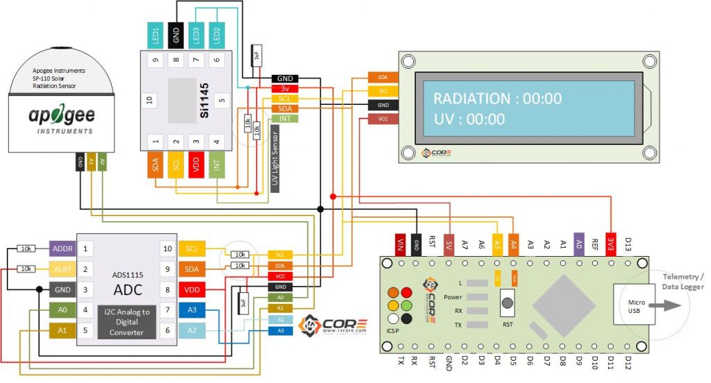
This illustration is based on Pyranometer/Actinometer. Pyranometer is a device that measures the solar irradiance of a planar surface or to measure the solar radiation flux density from the hemisphere above within a wavelength range. To achieve this instrument we will going to use a uv sensor (SU-100) from Apogee and (SI1145) from Silicon Labs. Ultraviolet Radiation is a fragments of electromagnetic spectrum measure from 100 to 400 NM, and subdivided intro 3 wavelength range of UV-A (315 ~ 400 NM) UV-B(280 ~ 315 NM) and UV-C (100 ~ 280 nm). Excellent for UV-B / UV-C wavelengths from the sun, captivated by the earth’s atmosphere. Most Ultraviolet sensors are offered to select a wavelength range or provides a broadband ultraviolet source, this UV sensors is designed for sunlight measurement featuring a highly sensitive to UV radiation in the UV-A and UV-B that can detect from 250 to 400 nm calibrated in photon flux units of micromoles per square meter in second. The sensor output can be also expressed in energy flux units of watts per square meter and equal to Joules per seconds per square meter.
As you can see the illustration there are 5 components the SU-100, SI1145, ADC (Analog to digital Converter), 16X2 LCD Display and the Microcontroller, purposely implemented for Microcontroller. However you can also use other devices such as SBC, ESP Series, STM32 and Micro-Python Boot loaded controller.
The ADC1115 is a chip that converts the Analog signal to a Digital signal and measure a voltage between 0.0v – 4.096v at default GAIN value. The solar radiation can scope a value of 1700Wm2 which is can generate a result to 0.34v converted to wave form signal output meaning you safely use an amplification of 8 – GAIN for measurement. However as you can see the diagram below the SU-100 pin A0 and A1 are connected to the ADC1115 Analog In, and require to read the differential value of A0 (Analog 0) and A1 (Analog 1) using signed integers output. The data will be -32767 ~ +32767 range, at the maximum measurable output at GAIN 4.096V and convert the value to voltage and multiply by a factor of 5000 to get the final radiation data into. Keep in mind that the SU-100 radiation sensor has a sensitivity of 20mV per Wm2 / (20mV per watt per square metre Wm2).
The SI1145 is a reflectance base IR, ultraviolet and ambient light sensor. This sensor can read a direct sunlight source or direct sunlight measuring the UV index scale. The SI1145 will also run under the glass covers which is expose to the open area, the photodiode will react and convert an excellent immunity to artificial light noise and natural light flutter noise. See the datasheet for more details. For this demonstration we will going to use a microcontroller to drive the SU-100 sensor along with the SI1145 and 16×2 LCD Screen for testing. See below the wiring guide and required components.
Required Components
- Arduino IDE | Atmel Studio | Energia | Processing
- Arduino PRO, FIO, NANO, UNO, MINI, MEGA, PRO MINI, LEO, BT, DUE, ETHERNET,LILYPAD, NodeMCU, Teensy Board, TeensyDuino, ESP8266 12, 12E, ESP32, ESP8266, Note: The Diagram below is using NANO. (please refer to each MCU’s respective pin-outs & bus configurations)
- Optional (MicroPython, Raspberry Pi, Begelbone, Beaglebone, Intel SBC)
- Apogee SU-100 Ultraviolet Sensor
- Silicon Labs SI1145
- ADC1115 (i2C Analog to Digital Converter)
- 16X2 / 20X4 i2c LCD Screen Display Panel
- Capacitors (See below required values)
- Resistors (See below required values)
- PCB Designer (Circuit simulation to PCB Layout)
- Telemetry Data Viewer > https://github.com/farrellf/Telemetry-Viewer
Wiring Guide
Source Code
Downloads
- Download APOGEE Datasheet
- Download APOGEE User Manual
- Download Silicon Labs SI1145 Datasheet
- Download ADC1115 Datasheet
- Download ADC1115 Code Library
- Download SI1145 Code Library
- Download 16×2 i2C LCD Display Code Library


Hello,
I have built this exactly as described above although i have used an arduino uno. The code wont get past the “Device Communication Error” if statement. what could be going wrong?
Kind regards
Rick
Ok, on which communication having an error? there are 3 devices connected to MCU, Radiance, UV, and Display panel, if the Radiance sensor is not communicating try to connect directly to the analog input to MCU alone without the UV and LCD, then try to read the signal coming from the analog input, if there is response then proceed to the next sensor. See to it that your serial communication is not used by other devices, however you can also isolate the serial communication by declaring the specified pins to your MCU board. :) regards
Hello,
I have question, why it use “multiplier = 0.1875F” when the gain “radianceSensor.setGain(GAIN_EIGHT);” ? why the multiplier is not “0.015625F”?
// ads.setGain(GAIN_EIGHT); // 8x gain +/- 0.512V 1 bit = 0.25mV 0.015625mV
Thanks,
Hi, I have a question. I compiled the program but this error occured. Saying,
no matching function for call to ‘max(int, double)’
Can somebody help me.