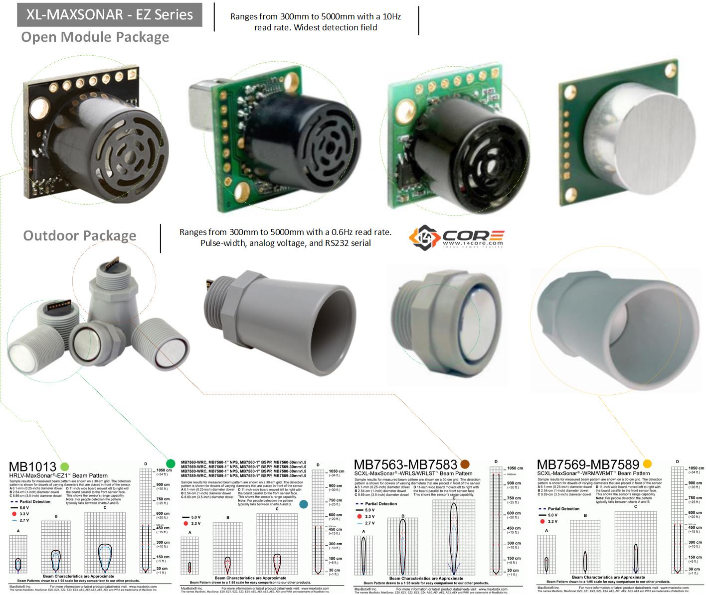
The XL-MaxSonar – EZ Series are high-performance industrial grade sonar ranging sensor, excellent sensitivity with a high side object rejection, can be use as short to long distance detection ranging. This module has a various output options, that supports PWM, ANALOG, RS232 or TTL Serial. These modules offer virtually noise free distance reading though the use of high-output acoustic power output merge with continuously variable gain, real-time background atomic calibration, real-time waveform examination, with noise rejection algorithm, object detection as close as 1mm from the sensor, supports 3.3v to 5.5v supply with very low average current draw, can be set as triggered operation to be set as reading range as desired.
XL-MAXSONAR-EZ SERIES
MB1200, MB1210, MB1220, MB1230, MB1240, MB1260, MB1261, MB1300, MB1310, MB1320, MB1330, MB1340, MB1360, MB1361, MB1003, MB1013, MB1023, MB1033, MB10436, MB1024, MB1004, MB1014, MB7560, MB7563, MB7566, MB7567, MB7569, MB7580, MB7583, MB7586, MB7587, MB7589.
The XL-MaxSonar can be implemented in most cases like level measurement, proximity detection, human detection, Robotics, Autonomous navigation, Environmental use, Multiple sensory arrays for specific projects, Distance Measurement, Long range object detection.
Pinouts Description:
PIN 1 – BW – Leave open (or high) for serial output on the Pin 5 output. When Pin 1 is held low the Pin 5 output sends a pulse (instead of serial data), suitable for low noise chaining.
PIN 2 – PW – For the MB1200 (EZ) sensor series, this pin outputs a pulse width representation of range. To calculate distance, use the scale factor of 58uS per cm.
For the MB1300 (AE) sensor series, this pin outputs the analog voltage envelope of the acoustic wave form. The output allows the user to process the raw waveform of the sensor.
PIN 3 – AN – For the 7.6-meter sensors (all sensors except for MB1260, MB1261, MB1360, and MB1361), this pin outputs analog voltage with a scaling factor of (Vcc/1024) per cm. A supply of 5V yields ~4.9mV/cm., and 3.3V yields ~3.2mV/ cm. Hardware limits the maximum reported range on this output to ~700cm at 5V and ~600cm at 3.3V. The output is buffered and corresponds to the most recent range data. For the 10-meter sensors (MB1260, MB1261, MB1360, MB1361), this pin outputs analog voltage with a scaling factor of (Vcc/1024) per 2 cm. A supply of 5V yields ~4.9mV/2cm., and 3.3V yields ~3.2mV/2cm. The output is buffered and corresponds to the most recent range data.
PIN 4 – RX – This pin is internally pulled high. The XL-MaxSonar-EZ sensors will continually measure range and output if the pin is left unconnected or held high. If held low it will stop the ranging. Bring high 20uS or more for range reading.
PIN 5 – TX – When Pin 1 is open or held high, the Pin 5 output delivers asynchronous serial with an RS232 format, except voltages are 0-Vcc. The output is an ASCII capital “R”, followed by three ASCII character digits representing the range in centimeters up to a maximum of 765, followed by a carriage return (ASCII 13). The baud rate is 9600, 8 bits, no parity, with one stop bit. Although the voltage of 0-Vcc is outside the RS232 standard, most RS232 devices have sufficient margin to read 0-Vcc serial data. If standard voltage level RS232 is desired, invert, and connect an RS232 converter such as a MAX232. Note: When Pin 1 is held low, the Pin 5 output sends a single pulse, suitable for low noise chaining (no serial data).
PIN 6 – VCC (3.3V ~ 5V) – The average (and peak) current draw for 3.3V operation is 2.1mA (50mA peak) and at 5V operation is 3.4mA (100mA peak) respectively. Peak current is used during sonar pulse transmit.
PIN 7 – GND (GROUND) – Return for the DC power supply. GND (& V+) must be ripple and noise free for best operation.
For more details regarding the configuration please refer to the datasheet below.
Required Component
- Arduino IDE | Atmel Studio | Energia | Processing
- Sony SPRESENSE Dev Board, Arduino PRO, FIO, NANO, UNO, MINI, MEGA, PRO MINI, LEO, BT, DUE, ETHERNET,LILYPAD, NodeMCU, Teensy Board, TeensyDuino, ESP8266 12, 12E, ESP32, LinkItOne, ESP8266 NodeMCU, ESPDuino, ATMEGA328 16/12, ATMEGA32u4 16/8/ MHz, ESP8266, MSP430 ,ATMEGA250 16 MHz, ATSAM3x8E, STM32.
- If your working with Sony SPRESENSE Please refer to this link
- Note: For AVR (please see the flash size of the MCU and respective pin-outs & bus configuration )
- Note: The Diagram below is using ATMEGA328TQFP. (please refer to each MCU’s respective pin-outs & bus configuration)
- VL53L1X Sensor /Module
- Capacitors (See below required value)
- Resistors (See below required value)
- Regulators (See below required value)
- TTL USB UART (Optional if your using s MCU USB/UART integrated)
- PCB Designer (Circuit simulator to PCB Layout / Circuitmaker / Autodesk Eagle / Fritzing )
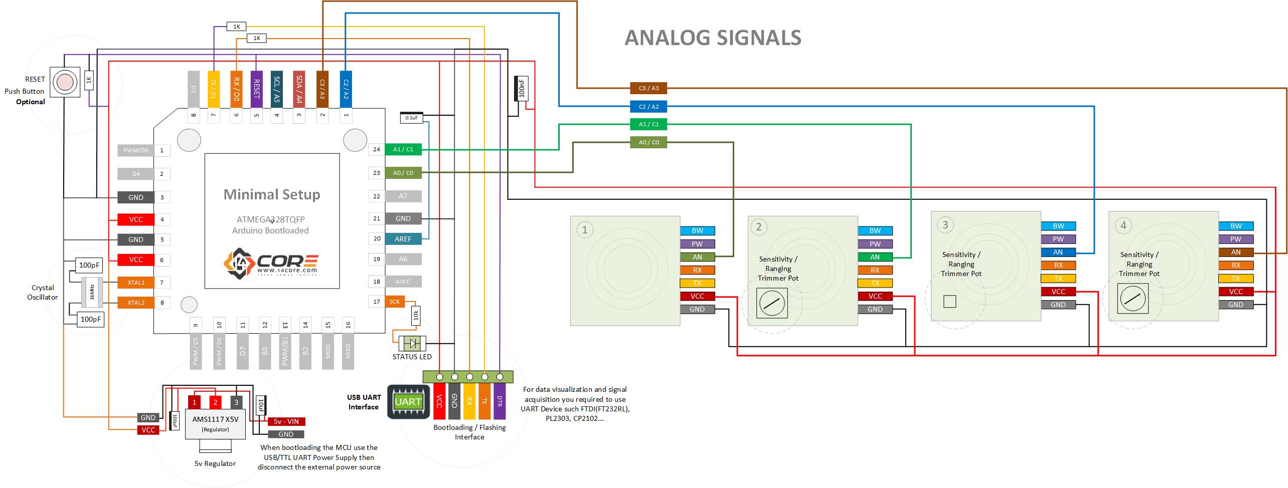
Analog Signal Wiring Guide
The circuit is purposely made as minimal configuration, just to communicate with does arrays sensor, for data acquisition you need to use a USB TTL UART Converter.
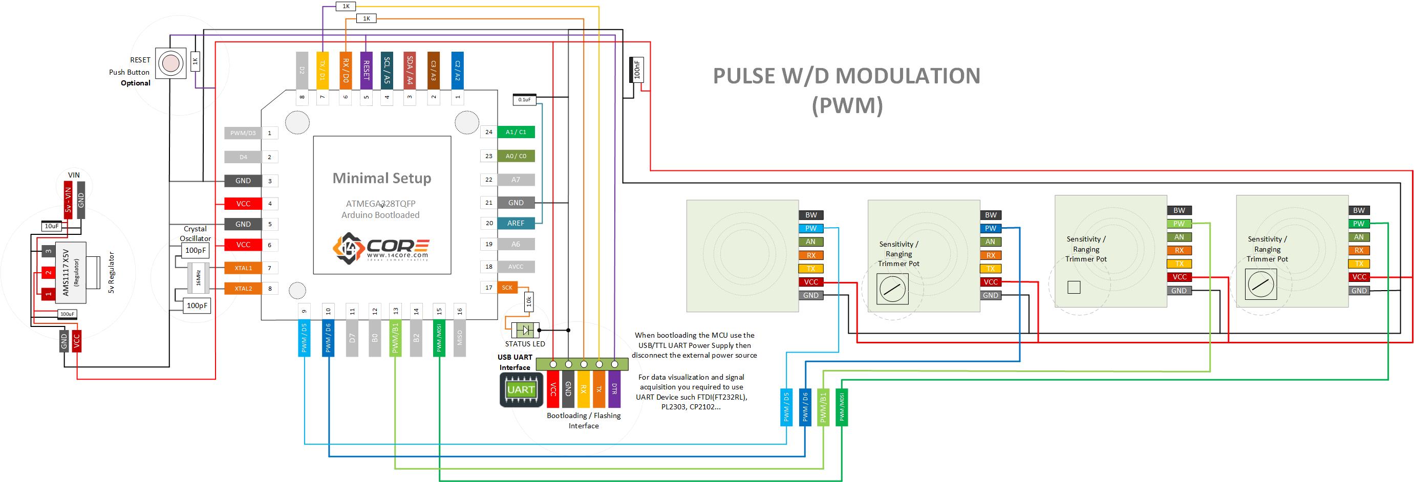
PWM Wiring Guide
Source Code for Analog
Ultrasonic sensor does not trigger every mS, and delays will slows down the mcu, it will pulls with new range at set intervals, this should be set the sensors read rate, 100mS at 10Hz rate.
Source Code for Pulse w/d Modulation


