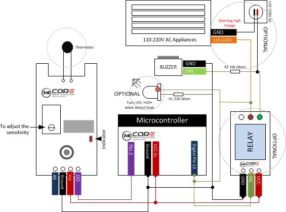
In this illustration we will going to wire the Digital Thermal / Temperature Sensor Module with Thermistor in Arduino, this module can be used to sense temperature or heat. It can be used either with or without Arduino, as you can see the schematics below there is an Optional Relay & Optional LED as status indicator which is connected to Arduino board.
Adjusting the Sensor Sensitivity
You can adjust the sensitivity of the thermistor sensor based on temperature by turning the potentiometer or the variable resistor using a screw driver. By rotating the potentiometers knob in clockwise direction after the onboard Led will turn off. In the way you can increase or decrease the sensitivity. If you keep on adjusting the knob even after the LED will turned off you will need more heat around the thermistor to turn it on.
When the temperature around the sensor increases the sensor module output a LOW signal and Arduino turn on the LED. In place of LED you can used 5v relay module to turn on the FAN or something works on 110-220V AC.
Note: When the Module LED is HIGH the output on pin DO is LOW, otherwise it is always HIGH
Required Components
Arduino UNO/MEGA/PRO/NANO
Temperature SensorModule
Solder Less Bread Board
Jumper Wires
Optional Components

5v Relay Module
1x Buzzer
1x 10k Resistor
1x 220k Resistor
Wiring Diagram
Arduino Sketch Code


