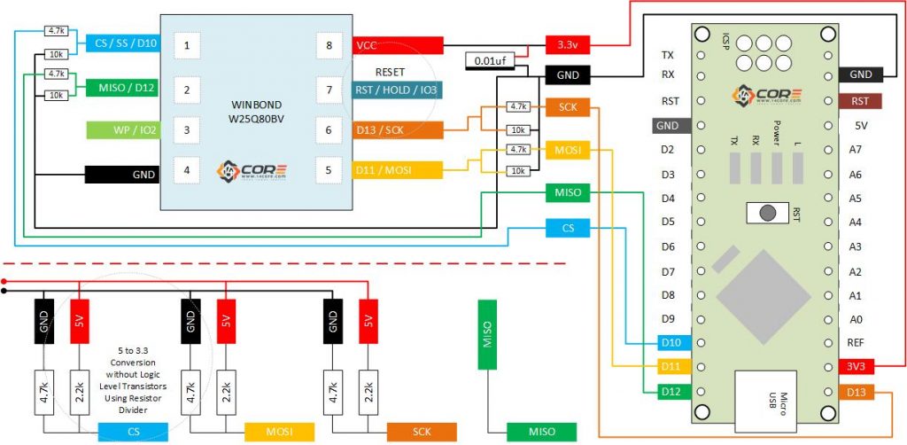
#include <SPI.h>
#define writeEnable 0x06 // Address Write Enable
#define writeDisable 0x04 // Address Write Disable
#define chipErase 0xc7 // Address Chip Erase
#define readStatusReg1 0x05 // Address Read Status
#define readData 0x03 // Address Read Data
#define pageProgramStat 0x02 // Address Status Page Program
#define chipCommandId 0x9f // Address Status Read Id
boolean g_command_ready(false);
String g_command;
/*
print_page_bytes() is a simple helper function that formats 256 bytes
*/
void print_page_bytes(byte *page_buffer) {
char buf[10];
for (int i = 0; i < 16; ++i) {
for (int j = 0; j < 16; ++j) {
sprintf(buf, "%02x", page_buffer[i * 16 + j]);
Serial.print(buf);
}
Serial.println();
}
}
/*
This functions map to user commands. wrap the low-level calls with
print/debug statements to read
*/
/*
The chip command id is fairly generic, just to verify function setup
*/
void chipCmdIda(void) {
Serial.println("Set Command: chipCmdIda");
byte b1, b2, b3;
chipCmdId(&b1, &b2, &b3);
char buf[128];
sprintf(buf, "ID: %02xh\nMemory Type: %02xh\nCapacity: %02xh",
b1, b2, b3);
Serial.println(buf);
Serial.println("Ready");
}
void chip_erase(void) {
Serial.println("command: chip_erase");
_chip_erase();
Serial.println("Ready");
}
void read_page(unsigned int page_number) {
char buf[80];
sprintf(buf, "command: read_page(%04xh)", page_number);
Serial.println(buf);
byte page_buffer[256];
_read_page(page_number, page_buffer);
print_page_bytes(page_buffer);
Serial.println("Ready");
}
void read_all_pages(void) {
Serial.println("command: read_all_pages");
byte page_buffer[256];
for (int i = 0; i < 4096; ++i) {
_read_page(i, page_buffer);
print_page_bytes(page_buffer);
}
Serial.println("Ready");
}
void write_byte(word page, byte offset, byte databyte) {
char buf[80];
sprintf(buf, "command: write_byte(%04xh, %04xh, %02xh)", page, offset, databyte);
Serial.println(buf);
byte page_data[256];
_read_page(page, page_data);
page_data[offset] = databyte;
_write_page(page, page_data);
Serial.println("Ready");
}
void chipCmdId(byte *b1, byte *b2, byte *b3) {
digitalWrite(SS, HIGH);
digitalWrite(SS, LOW);
SPI.transfer(chipCommandId);
*b1 = SPI.transfer(0); // manufacturer id
*b2 = SPI.transfer(0); // memory type
*b3 = SPI.transfer(0); // capacity
digitalWrite(SS, HIGH);
not_busy();
}
/*
See the timing diagram in section 9.2.26 of the data sheet, "Chip Erase (C7h / 06h)". (Note:
*/
void _chip_erase(void) {
digitalWrite(SS, HIGH);
digitalWrite(SS, LOW);
SPI.transfer(writeEnable);
digitalWrite(SS, HIGH);
digitalWrite(SS, LOW);
SPI.transfer(chipErase);
digitalWrite(SS, HIGH);
/* See notes on rev 2
digitalWrite(SS, LOW);
SPI.transfer(writeDisable);
digitalWrite(SS, HIGH);
*/
not_busy();
}
/*
* See the timing diagram in section 9.2.10 of the
* data sheet located below, "Read Data (03h)".
*/
void _read_page(word page_number, byte *page_buffer) {
digitalWrite(SS, HIGH);
digitalWrite(SS, LOW);
SPI.transfer(readData);
// Construct the 24-bit address from the 16-bit page
// number and 0x00, since we will read 256 bytes (one
// page).
SPI.transfer((page_number >> 8) & 0xFF);
SPI.transfer((page_number >> 0) & 0xFF);
SPI.transfer(0);
for (int i = 0; i < 256; ++i) {
page_buffer[i] = SPI.transfer(0);
}
digitalWrite(SS, HIGH);
not_busy();
}
/*
* See the timing diagram in section 9.2.21 of the
* data sheet, "Page Program (02h)".
*/
void _write_page(word page_number, byte *page_buffer) {
digitalWrite(SS, HIGH);
digitalWrite(SS, LOW);
SPI.transfer(writeEnable);
digitalWrite(SS, HIGH);
digitalWrite(SS, LOW);
SPI.transfer(pageProgramStat);
SPI.transfer((page_number >> 8) & 0xFF);
SPI.transfer((page_number >> 0) & 0xFF);
SPI.transfer(0);
for (int i = 0; i < 256; ++i) {
SPI.transfer(page_buffer[i]);
}
digitalWrite(SS, HIGH);
/* See notes on rev 2
digitalWrite(SS, LOW);
SPI.transfer(writeDisable);
digitalWrite(SS, HIGH);
*/
not_busy();
}
/*
* See section 9.2.8 of the datasheet
*/
void not_busy(void) {
digitalWrite(SS, HIGH);
digitalWrite(SS, LOW);
SPI.transfer(WB_READ_STATUS_REG_1);
while (SPI.transfer(0) & 1) {};
digitalWrite(SS, HIGH);
}
/*
* string, setting a boolean used by the loop() routine
* as a dispatch trigger.
*/
void serialEvent() {
char c;
while (Serial.available()) {
c = (char)Serial.read();
if (c == ';') {
g_command_ready = true;
}
else {
g_command += c;
}
}
}
void setup(void) {
SPI.begin();
SPI.setDataMode(0);
SPI.setBitOrder(MSBFIRST);
Serial.begin(9600);
Serial.println("");
Serial.println("Ready");
}
/*
*/
void loop(void) {
if (g_command_ready) {
if (g_command == "chipCmdIda") {
chipCmdIda();
}
else if (g_command == "chip_erase") {
chip_erase();
}
else if (g_command == "read_all_pages") {
read_all_pages();
}
// A one-parameter command...
else if (g_command.startsWith("read_page")) {
int pos = g_command.indexOf(" ");
if (pos == -1) {
Serial.println("Error: Command 'read_page' expects an int operand");
} else {
word page = (word)g_command.substring(pos).toInt();
read_page(page);
}
}
// A three-parameter command..
else if (g_command.startsWith("write_byte")) {
word pageno;
byte offset;
byte data;
String args[3];
for (int i = 0; i < 3; ++i) {
int pos = g_command.indexOf(" ");
if (pos == -1) {
Serial.println("Syntax error in write_byte");
goto done;
}
args[i] = g_command.substring(pos + 1);
g_command = args[i];
}
pageno = (word)args[0].toInt();
offset = (byte)args[1].toInt();
data = (byte)args[2].toInt();
write_byte(pageno, offset, data);
}
else {
Serial.print("Invalid command sent: ");
Serial.println(g_command);
}
done:
g_command = "";
g_command_ready = false;
}
}


How do i write a command,i cant get it to work,can you show an example,ive tryed this chip_erase it doesnt work does it need to be like this “chip_erase” or : “chip_erase” ive tryed everything.thanks
See the timing diagram in section 9.2.26 of the data sheet, “Chip Erase (C7h / 06h) / See the datasheet for the SPI timing. you can execute the wire command address 0xC7.
void _chip_erase(void) {
digitalWrite(SS, HIGH);
digitalWrite(SS, LOW);
SPI.transfer(writeEnable);
digitalWrite(SS, HIGH);
digitalWrite(SS, LOW);
SPI.transfer(chipErase);
digitalWrite(SS, HIGH);
I get the following error compiling for nano;
‘WB_READ_STATUS_REG_1’ was not declared in this scope
So do I.. Cannot get the sketch to work no matter what. Since the W25Q80BV is no longer manufactured I am using a W25X20CL, it is very very small and difficult to solder wires to, But even it does nothing. Only prints READY and that is the end. How should it work??
Thank you
In the #define section you can find the following definition:
#define readStatusReg1 0x05 // Address Read Status
Just edit the line 172 and replace SPI.transfer(WB_READ_STATUS_REG_1); line
with the nex line:
SPI.transfer(readStatusReg1);
j’ai besion ce fichier flash w25q80dv