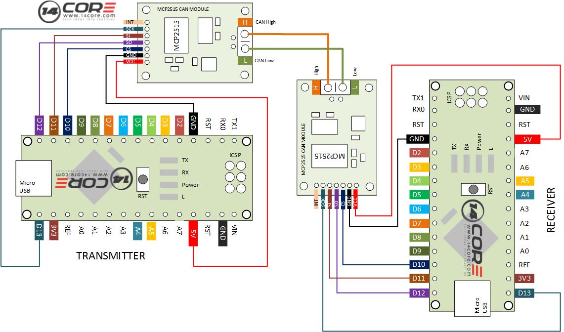
Wiring the MCP2515 Stand-alone CAN Controller with SPI
This is an illustration how CAN (Controller Area Network) protocol interface works with Microcontroller. CAN protocol is methodology of communication between electronics devices, commonly found in Automotive, these device is the responsible for the car engine management system, Gear Control, Active Suspension, ABS, Lightning and Control, Air Condition, Air Bags, Security System, Central Locking, ETC. As you can see below diagram its uses 2 microcontroller and 2 CAN module here you will see how microcontroller interface with CAN (MCP2515) and drive as 2 wire RX/TX base data communication.
The MCP2515 is a stand-alone CAN Controller Area Network that implements the CAN specification v2.0B. These device is capable of transmitting and receiving both standard and extended data/remote frames and it has standard SPI (Serial Peripheral Interface). MCP2515 has 2 acceptance mask and 6 acceptance filters that are used to filter out unwanted messages, reducing the host MCU overhead.
Required Component
2x Arduino Micro-controller
2x MCP2515 Module
Jumper Wires / DuPont Wires
Solder-less Breadboard
Wiring Diagram
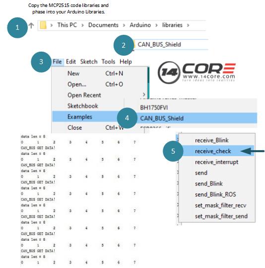
Importing the required code libraries
Test Code / Test Sketch Code
1
2
3
4
5
6
7
8
9
10
11
12
13
14
15
16
17
18
19
20
21
22
23
24
25
26
27
28
29
30
31
32
33
34
35
36
37
38
39
40
41
42
43
44
45
46
47
48
49
50
51
52
53
// demo: CAN-BUS Shield, receive data with check mode
// send data coming to fast, such as less than 10ms, you can use this way
#include <SPI.h>
#include "mcp_can.h"
// the cs pin of the version after v1.1 is default to D9
// v0.9b and v1.0 is default D10
constintSPI_CS_PIN=10;// Default is 9
MCP_CAN CAN(SPI_CS_PIN);// Set CS pin
voidsetup()
{
Serial.begin(115200);// Set baud rate 115200
START_INIT:
if(CAN_OK==CAN.begin(CAN_500KBPS))// init can bus : baudrate = 500k
{
Serial.println("14CORE | CAN BUS TEST CODE");
Serial.println("CAN BUS MODULE IS RUNNING");
Serial.println("..........................");
}
else
{
Serial.println("CAN BUS MODULE NOT RESPONDING");
Serial.println("INITIALIZING CAN MODULE PLEASE WAIT...");
delay(100);
gotoSTART_INIT;
}
}
voidloop()
{
unsignedcharlen=0;
unsignedcharbuf[8];
if(CAN_MSGAVAIL==CAN.checkReceive())// check if data coming
{
CAN.readMsgBuf(&len,buf);// read data, len: data length, buf: data buf
We use cookie to provide you the best possible experience, this site uses cookies and by continuing to use the site you agree that we can save them on your device. Cookies are small text files which are placed on your computer and which remember your preference / some details of your visit. Our cookies don’t collect any personal information. For information, please read our Privacy Statement and Cookie Policy , which also explains how to disable this option in your browser. Cookie SettingsACCEPT
Privacy & Cookies Policy
Privacy Overview
This website uses cookies to improve your experience while you navigate through the website. Out of these cookies, the cookies that are categorized as necessary are stored on your browser as they are as essential for the working of basic functionalit...
Necessary cookies are absolutely essential for the website to function properly. This category only includes cookies that ensures basic functionalities and security features of the website. These cookies do not store any personal information.
Any cookies that may not be particularly necessary for the website to function and is used specifically to collect user personal data via analytics, ads, other embedded contents are termed as non-necessary cookies. It is mandatory to procure user consent prior to running these cookies on your website.