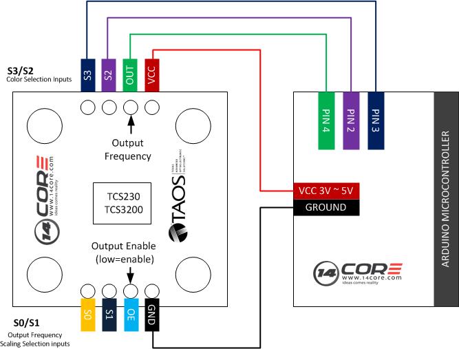
This illustration we will going to wire the TCS230/TCS3200 chip module board this boards is designed to detect the colors, it has an array of photodiode 8×8 matrix. These photodiodes are covered with four type of filters. The TCS230/TCS320 converts the intensity of incident radiation into frequency. The output waveform is 50% duty cycle square wave. You can use the timer from the MCU to measure period of pulse and get the color frequency. The output of TCS230/3200 is available in single line. So you well get the intensity of RED, GREEN, BLUE and Clear channels.
Component Required
Arduino UNO/MEGA/NANO/PRO
TCS320 / TCS230 Module Board
Solder less Breadboard
Jumper Wires
Wiring Diagram
Arduino Sketch Code
[crayon-690bab27633a1984360723/]
Download the TCS320 datasheet here | Pdf
Download the TCS3200/TCS3210 datasheet here | Pdf


