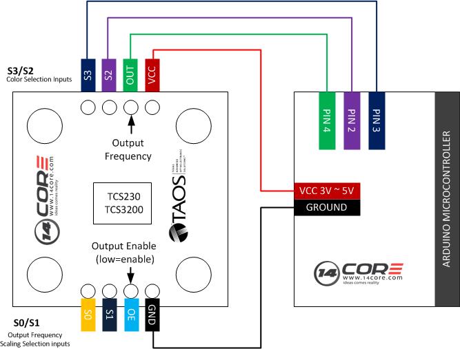
This illustration we will going to wire the TCS230/TCS3200 chip module board this boards is designed to detect the colors, it has an array of photodiode 8×8 matrix. These photodiodes are covered with four type of filters. The TCS230/TCS320 converts the intensity of incident radiation into frequency. The output waveform is 50% duty cycle square wave. You can use the timer from the MCU to measure period of pulse and get the color frequency. The output of TCS230/3200 is available in single line. So you well get the intensity of RED, GREEN, BLUE and Clear channels.
Component Required
Arduino UNO/MEGA/NANO/PRO
TCS320 / TCS230 Module Board
Solder less Breadboard
Jumper Wires
Wiring Diagram
Arduino Sketch Code
1 2 3 4 5 6 7 8 9 10 11 12 13 14 15 16 17 18 19 20 21 22 23 24 25 26 27 28 29 30 31 32 33 34 35 36 37 38 39 40 41 42 43 44 45 46 47 48 49 50 51 52 53 54 55 56 57 58 59 60 61 |
/*__________________________________________________________ $$$$$$$$$$$$$$$$$$$$$$$$$$$$$$$$$$$$$$$$$$$$$$$$$$$$$$$$$$$$ 14CORE.com ARDUINO COLOR SENSOR TCS230/TCS3200 $$$$$$$$$$$$$$$$$$$$$$$$$$$$$$$$$$$$$$$$$$$$$$$$$$$$$$$$$$$$ ____________________________________________________________ */ enum Colours {RED,GREEN,BLUE,CLEAR}; //Unumerate Colours RED,GREEN,BLUE and ClEAR #define s2Pin 2 //S2 Colour Selection inputs define and connected to arduino pin 2 #define s3Pin 3 //S3 Colour Selection inputs define and connected to arduino pin 3 #define outPin 4 //Output define in Arduino pin 4 void setup() { Serial.begin(9600); //Serial begin at baudrate 9600 pinMode(s2Pin, OUTPUT); //Pin Mode s2Pin as Output pinMode(s3Pin, OUTPUT); //Pin Mode s2Pin as Output pinMode(outPin, INPUT); //Pin Mode s2Pin as Input } void loop() { Serial.print(ReadColour(RED)); //Read colors value to serial communication Serial.print(" : "); Serial.print(ReadColour(GREEN)); Serial.print(" : "); Serial.print(ReadColour(BLUE)); Serial.print(" : "); Serial.println(ReadColour(CLEAR)); } // Function reads colours and returns the a value betwenn 0 and 255 byte ReadColour(byte Colour) { switch(Colour) { case RED: digitalWrite(s2Pin, LOW); digitalWrite(s3Pin, LOW); break; case GREEN: digitalWrite(s2Pin, HIGH); digitalWrite(s3Pin, HIGH); break; case BLUE: digitalWrite(s2Pin, LOW); digitalWrite(s3Pin, HIGH); break; case CLEAR: digitalWrite(s2Pin, HIGH); digitalWrite(s3Pin, LOW); break; } return map(pulseIn(outPin, HIGH), 30, 2500, 255, 0); //PWM map to 30,2500,255,0 } |
Download the TCS320 datasheet here | Pdf
Download the TCS3200/TCS3210 datasheet here | Pdf
Olá, sou do Brazil e este tutorial me ajudou muito… Já estava desesperado. Agradeço!