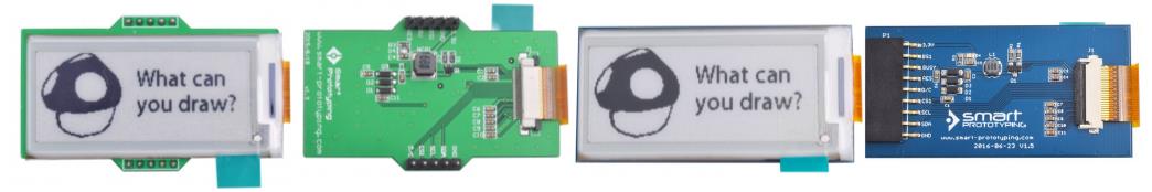
This is the E-Ink display module designed for ink display development. This module can work without additional electronic parts you just plug the module directly to your microcontroller. This device has driven by SSD1606 4GS active matrix display driver selectable at 6800 – /8080 series via Parallel Interface or Serial Peripheral Interface. SSD1606 is a CMOS active matrix bitable display driver with controller it has 129 source output and 1180 gat output, 1VCOM, 1VBD for border that support 128×180 resolution with integrated booster, regulator, and oscillator that runs on 2.4 ~ 3.3v with super wide viewing angle near 180 degree, 172×72 resolution in 4 gray shade color in an extra light and thin. As an example we used a NANO board for testing but you can also use Arduino UNO and some other microcontroller that runs on Arduino IDE. For further product details See below the datasheets.
Required Components
- Arduino Microcontroller, NodeMCU, Teensy Board, TeensyDuino, ESP8266 12, 12E, ESP8266 NodeMCU, ESPDuino, ATMEGA328 16/12, ATMEGA32u4 16/8/ MHz, ESP8266, ATMEGA250 16 MHz, ATSAM3x8E, ATSAM21D, ATTINY85 16/8 MHz (Note: The Diagram below is using NANO. (please refer to the respective pin-outs)
- E Ink 172×72 Gray Shade Electronic Ink Module
- Jumper Wires / DuPont Wires
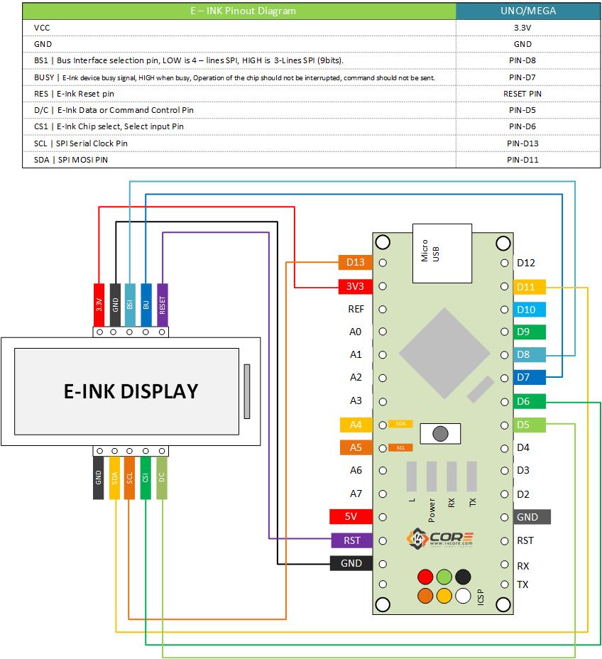
Wiring Guide
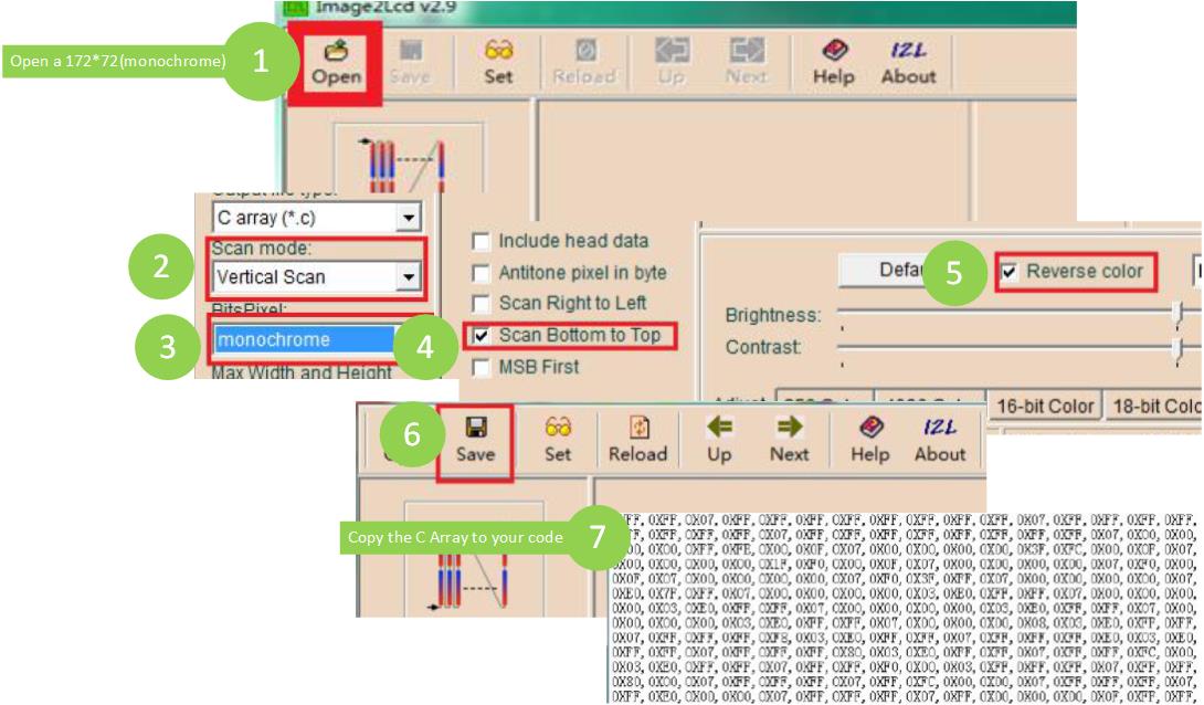
Generating C-Code Array for Bitmaps Images
Source Code
|
1 2 3 4 5 6 7 8 9 10 11 12 13 14 15 16 17 18 19 20 21 22 23 24 25 26 |
#include <SmartEink.h> // You can download this library below #include <SPI.h> // Import SPI Library E_ink Eink; //Set E-Ink SPI Address void setup() { pinMode(8,OUTPUT); //Set pin 8 as output digitalWrite(8, LOW); //Set pin 8 as off Eink.InitEink(); // Call function Eink.ClearScreen();// set to clear e-ink screen Eink.EinkP8x16Str(14,8,"14CORE.com"); Eink.EinkP8x16Str(10,8,"I-INK Test Code"); Eink.EinkP8x16Str(6,8,"0123456789"); Eink.EinkP8x16Str(2,8,"ABCDEFG abcdefg"); Eink.RefreshScreen(); } void loop() { } |
Downloads
Download Img2LCD C Code Array Generator | Zip
Download Smart E-Ink Code Library | Zip
Download SSD1606 Datasheet | PDF


Pingback:Wiring the SPI Electronic Ink / Electronic Paper Display Panel | 14Core.com
Pingback:LuminOx O2 / Oxygen UART Optical Sensor Arduino | 14Core.com