In this illustration we will going to test and wire the rotary encoder. Rotary encoder can be counted in the positive direction and the reverse direction during the rotation of the output pulse frequency and the rotation is continuous. Compare to rotary potentiometer this device has a limited rotation. The rotary encoder has its own push button built-in into the device itself, with the press of the button the encoder can be reset to its initial state, that start counting from 0 (ZERO).
The incremental encoder is a displacement of the rotary pulse signal when it’s converted to series of digital rotating sensor. These pulse are used to control angular displacement. The angular displacement encoder conversion using photoelectric scanning principle. Reading the system of alternating light transmission window and the windows is not consisting of radial indexing plate rotating basis, when the infrared light source vertical irradiation light to the code disk image into the receiving.
At the surface the receiver is covered with diffraction grating, which has the same code disk window width. The receiver task is to feel the rotation of the disk creating a changes into the corresponding light electrical change and the low level signal up to a high level, along with the generation of square pulse, which must be processed by electric circuit. Reading the system typically employ a differential manner, and which the same but the phase is different of the two waveform by 180 degree compare to the signal in order to improve the stability of the output signal, reading should be formed on the basis to eliminate the interference.
The incremental encoders produce a series of pulses. These pulse are used to measure the rotation, position of the shaft, and velocity. There are two channel of rotary encoder output (A and B in US terminology). The encoder signals are offset from one another by ½ of a pulse. Sometimes this is also referred to a 90 degree phase separation. This term comes from discussing one entire encoder pulse cycle, from when the signal first rises up, to where it rises up again as 360 degrees. Then you can see that the distance of ½ of encoder pulse would be considered 90 degrees.
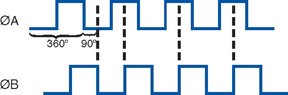
As you can see the illustration above there are two quadrature channel, and separated by 90 degrees, the user of the rotary encoder often wants to know the direction of rotation. Encoder manufacturers publish their specification for which signal comes first by specifying the direction of rotation.

The incremental encoders has two phase the square wave the phase difference between 90 degree, often referred as A and B channel. One of the channel is providing a speed related information at the same time by sequentially comparing two channel signals, the direction of rotation and the information obtained. There is also special signal called Z or ZERO channel, which gives the absolute zero rotary position, the signal shows a square wave with the center line of channel A square wave coincide. Incremental encoder accuracy depends on the mechanical electrical two factors, these factors are (RASTER INDEXING ERROR), (DISC ECCENTRICITY), (BEARING ECCENTRICITY), To know how much electrical equivalent of the mechanical angle of 360 degrees can be calculated with the following formula below.

A & B Commutation Signals
Encoder indexing error is the electrical angle of the unit of two successive pulse maximum offset. Error exist in encoding which is caused by the aforementioned factors. The maximum error will be ± 25 electrical degrees (declared in any condition), equivalent to the rated offset value ± 7%, as the phase 90 degree electrical of two channels and the maximum deviation ± 35 electrical degrees is equal to ± 10% deviation left Ratings Right.

Required Components
- Arduino Board
- Rotary Encoder Module Board / Rotary Encoder
- 1x Red Led
- 1x Green Led
- 1x Yellow Led
- 3x 220k Ohms Resistor
- Solder Less Bread Board
- Jumper / DuPont Wires
Wiring Diagram Pinout

Sketch Code


i want to use a pwm motor controller to run a 2 volt motor, if i put 2 pots in line. one pot would rotate 100% the second would be set at 70% no matter what the motor will run at 70% if i turned the first pot 0 to 100% i want to be able to cut back on the out put voltage or set for what ever voltage i want and it would stay at lets say 11 volts or 11.2 volts until i moved the second pot to another possition.