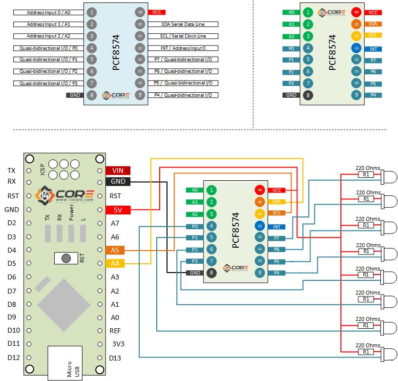
Wiring the PCF8574AP 8bit Bidirectional IO Expander Driven i2C Communication Bus / SPI
This is the PCF8574AP consists of an 8-bit quasi-bidirectional port and an i2C Serial Bus Interface. The PCF8574AP has a low current consumption and includes latched output with HIGH consumption and include latched output with high current drive capability for directly driving LEDS. It also possesses an interrupt which can be connected to the interrupt logic of the Microcontroller, by sending an interrupt signal on this line, the remote I/O can inform the microcontroller if there is incoming data on its ports without having to communicate via the i2C bus. This means that the PCF8574 can remain a simple slave device. This device is useful when you want to extend the IO pins of your Microcontroller using i2C Serial Communication Bus or SPI.
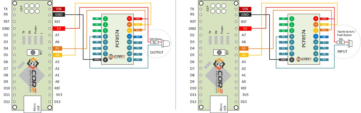
The Integrated PCF8574AP providing 8 ports INPUT / OUTPUT ports that can be manage using i2C serial communication. The following diagram below shows how to wire the PCF8574AP using OUTPUT series of LED served as indicator of our IO pins there are two diagram shows below one is the LED output and the tactile push button switch served as INPUT.
We use cookie to provide you the best possible experience, this site uses cookies and by continuing to use the site you agree that we can save them on your device. Cookies are small text files which are placed on your computer and which remember your preference / some details of your visit. Our cookies don’t collect any personal information. For information, please read our Privacy Statement and Cookie Policy , which also explains how to disable this option in your browser. Cookie SettingsACCEPT
Privacy & Cookies Policy
Privacy Overview
This website uses cookies to improve your experience while you navigate through the website. Out of these cookies, the cookies that are categorized as necessary are stored on your browser as they are as essential for the working of basic functionalit...
Necessary cookies are absolutely essential for the website to function properly. This category only includes cookies that ensures basic functionalities and security features of the website. These cookies do not store any personal information.
Any cookies that may not be particularly necessary for the website to function and is used specifically to collect user personal data via analytics, ads, other embedded contents are termed as non-necessary cookies. It is mandatory to procure user consent prior to running these cookies on your website.