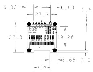
In this illustration we will going to wire the 128×64 OLED display screen, using SPI and I2C. As you can see the diagram below we used the Pin 5 to Pin 8 in Arduino Microcontroller to wire our OLED Display screen.
This display module has only 0.96” diagonal made of 128×64 OLED pixels, this module it works without backlight can be visible in the dark environment, OLED display is higher compared to LCD display. This OLED Display driven by SSD1306 chip compatible with i2C or SPI Bus communication, as you can see there are 2 resistors at the back of the module and sick-screen to see how to set the communication mode, the default mode is 4wire SPI mode except VCC and GND, 4wires would be need when using 4wires SPI mode. You can also set to the I2C mode, in which mode 2 control wires is needed.
Two types of version for this device
i2C
- GND
- VCC
- SCL
- SDA
SPI
6 Pins!, note SCL=CLK, SDA=MOSI, not IIC pins
- GND
- VCC
- CLK (SCL)
- MOSI(SDA)
- CS (chip select)
- D/C
Required Components
1x Arduino UNO/MEGA/LEO/NANO/PRO
1x 128×64 OLED Display Screen Module
1x Solder Less Bread Board
1x Jumper Wires
Wiring Diagram
Arduino Sketch
[crayon-68d200c665a36108060217/]
Download the download code library here | Zip
Download the SSD1780 Datasheet here | Pdf
Download the Image to byte array Generator | Download Area


