In this illustration we will going to wire the Arduino Board to build a remote switching using the NORDIC NRF24l01 2.4GHz Transceiver. The NRF24l01 will act as a remote controller to other NRF24L01. Both the master and the slave will drive by the Arduino boards along with and the NORDIC NRF24l01 RF Module. The host/master controller will send a signal command to the slave device and the slave device will execute the code and send back the response if the command is HIGH or LOW.
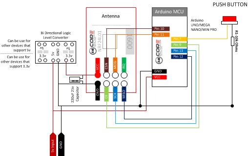
As you can see the illustration below we use the bi-directional logic level converter as our power supply to provide 3.3v to the NRF4L01 Radio module.
Required Components:
2x Arduino UNO/MEGA/NANO/PRO
2x NRF24L01 2.4GHz Transceiver Module (3.3v)
2x Solder Less Bread Board
2x 220 uF capacitor
1x Logic Level Converter
2x LED
2x 220k Resistor
Jumper Wire / DuPont Wire
Optional Component: Relay Module
(If you want to drive higher voltage such as light or appliances that runs on higher load)
Wiring Diagram for Transmitter
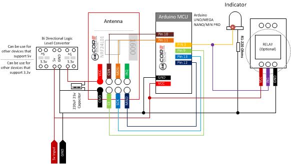
Wiring Diagram for Receiver
Arduino Sketch Code for the TX
|
1 2 3 4 5 6 7 8 9 10 11 12 13 14 15 16 17 18 19 20 21 |
/* 14CORE NRF24L01 MASTER CONTROLLER/TRANSMITTER */ #include <SPI.h> //Include SPI Code Library which can be downloaded below #include "nRF24L01.h" //Include NRF24L01 Code Library which can be downloaded below #include "RF24.h" //Inlcude NRF24 Code Library which can be downloaded below int msg[1]; RF24 radio(9,10); // The NRF24L01 Pin CE and Pin CSN const uint64_t pipe = 0xE8E8F0F0E1LL; //Communication Pip Address int switchButton = 7; // Push button connected to Arduino pin 7 void setup(void){ Serial.begin(9600); //Start Serial Communication at baud rate 9600 radio.begin(); radio.openWritingPipe(pipe);} //Open Communication Pipe void loop(void){ if (digitalRead(switchButton) == HIGH){ // When the push button has been press it will send radio signal to the RX to turn the LED into HIGH msg[0] = 111; //Send the 111 to the reciever radio.write(msg, 1);}} |
Arduino Sketch Code for the RX
|
1 2 3 4 5 6 7 8 9 10 11 12 13 14 15 16 17 18 19 20 21 22 23 24 25 26 27 28 29 30 |
/* 14CORE NRF24L01 SLAVE/RECIEVER */ #include <SPI.h> //Include SPI Code Library which can be downloaded below #include "nRF24L01.h" //Include NRF24L01 Code Library which can be downloaded below #include "RF24.h" //Inlcude NRF24 Code Library which can be downloaded below int msg[1]; RF24 radio(9,10); // NRF24L01 Pin const uint64_t pipe = 0xE8E8F0F0E1LL; //Start Pipe Communication Address int Indicator = 3; //This the LED which is connected to Arduino Pin 3 void setup(void){ Serial.begin(9600); radio.begin(); radio.openReadingPipe(1,pipe); radio.startListening(); pinMode(Indicator, OUTPUT);} void loop(void){ if (radio.available()){ bool done = false; while (!done){ done = radio.read(msg, 1); Serial.println(msg[0]); if (msg[0] == 111){delay(10);digitalWrite(Indicator, HIGH);} else {digitalWrite(Indicator, LOW);} delay(10);}} else{Serial.println("Error: No Radio Transmission");}} |
Download NRF24 Code Library Here | Zip
Download NRF24L01 Code Library Here | Zip


Is there a way to make this with multiple inputs and multiple outputs? Forgive me I am a beginner at this
Multiple I/O at the board? No, The NRF24l01 it is a communication device that works on 2.4Ghz, please refer to the documentations from the official Nordic Semiconductor,
but you can setup a multiple IO driven by the MCU from the MCU itself you can trigger any I/O which is transmitted from the NRF24l01 TX Role. Regards…
My Apologies, perhaps I was unclear. My goal would to be to have this exact setup but with maybe 3 push buttons on the transmitter and 3 leds on the receiver, and be able to use them all at the same time (being able to push 2 buttons at once and having 2 leds on at once, or 1 and 1, 3 and 3 etc.)
I just tried using the example and it had the weird effect that basically any pin on the TX could be driven high and send a signal over to the RX, I fixed this by setting the input pin high in the setup and having it check for the pin to be low for a transmission to start, this fixed the problem with that, But I would still like to be able to figure out how to have multiple buttons control multiple leds at the same time on the RX
pato amigo como vas,estoy tratando de hacer funcionar esto compadre,pero me sale un error en el sketh del receptor exactamente aqui
void loop(void){
if (radio.available()){
bool done = false;
while (!done){
radio.read(msg, 1);
Serial.println(msg[0]);
if (msg[1] == 111){delay(10);digitalWrite(Indicator, HIGH);}
else {digitalWrite(Indicator, LOW);}
delay(100);}}
else{Serial.println(“Error: No Radio Transmission”);}}
mira que la linea radio.read yo le quite el done=
y se quita el error pero me sale una lista de 0 en el monitor serial y 255 y asi sucesivamente,no se si lograstes solucionarlo estoy tambien empesando si puedes me escribes a mi correo aver si me echas una mano..
[email protected]
soy luiscarlos
Can someone extend the code for 6 buttons and 6 leds because i dont know how to do it i just started with the programming ..