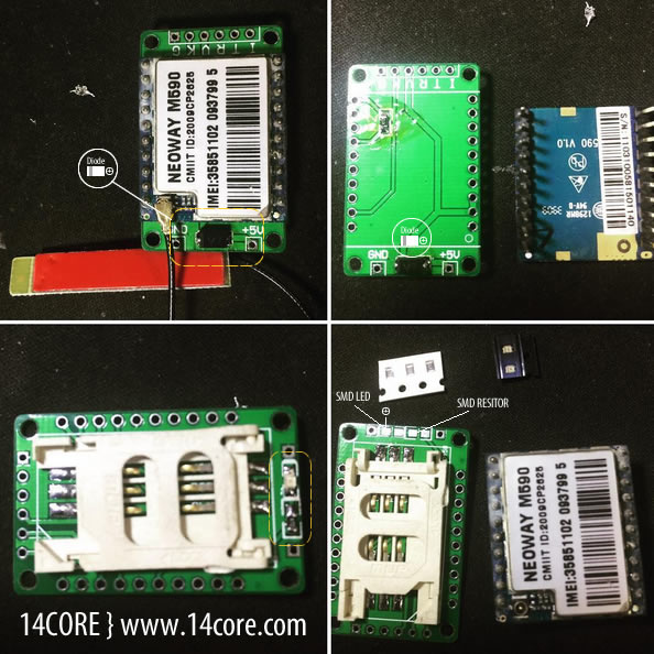
This is the M590 pure-data communication module an ultra compact GSM/GPRS industrial wireless module, optional dual-band or quad-band. It provides a high-quality SMS, GPRS data connection for use in industrial and commercial field.
Block Diagram of NEOWAY M590 GSM/GPRS Module
This module uses 2.8v IO power system, the maximum input voltage of all IO (Input Output) interface cannot be exceed to 3.3v otherwise the IO may be damage. The IO interface with a 3.3v power supply may for various reasons output at 3.3 or higher. In this event this voltage on the IO signal interface will connect to the IO of the 2.85v module and damage the IO ports. Resistor in series with these port should be used, as well as capacitors and filters.
As you see the schematics above it uses 1000uf low ESR aluminum electrolytic capacitors these capacitors are recommended for C1. should volume or space be limited to 470uf tantalum capacitor may be used. If the power source is connected to lithium batteries, a lower value capacitor at 100uF tantalum can be used as the batteries will be able to supply the peak instantaneous current. Maximum current draw will occur during the process of calling or data transmission in weak signal environment.
You need to make it sure that the instantaneous voltage does not drop lower than 3.3v during operation otherwise the device module will power off for self protection. keep in mind that you need to keep the power source far away from the RF (Radio Frequency section and ensure that 2A of current will be delivered safely with no obvious circuit drop. Routing the VBAT track should be approximately 2mm, each digital IO including serial port signal/light, and SIM card signal has integrated ESD over voltage protection, or an input level clamping circuit.
Frequency Bands: EGSM900/SCS1800 DUAL BAND, GSM850/1900, QUAD BAND
Sensitivity: -107dBm
Maximum Transmission Power: EGSM900 Class 4 2 Watts / DCS1800 Class 1 1 Watts
Instantaneous Current: MAX 2Amp
Operating Current: 210mA
Sleep Mode Current: 2.5mA
Working Temperature: -40 Degree Celsius to +85 Degree Celsius
Operating Voltage: 3.3v Recommended
Protocol: Compatible with GSM/GRPS Phase 2/2 + increased TCP/IP, FTP, UDP ETC
AT: GSM07.7 / Extended Command Sets.
Short Messaging: Text / PDU / Point to Point / Cell Broadcast
Group Data: GPRS CLASS 10 / Coding Mode-CS1, CS2, CS3, CS4
Circuit Switched Data: Support CSD(Circuit Switch Data Service) / Support USSD
Assembly Guide
Wiring with TTL UART USB
Wiring with Arduino MCU

Source Code / Sketch Code ( Sending SMS via Serial Communication )
Download Datasheet Block Diagram | PDF
Download AT-Command | PDF


Hi Dude,
Thank for your tutorial,
There are errors in your code, the compilation fail…
Can you correct them please ?
Thx
Hi,
How to use M590E as a TCP Server.
Thaks….
Here is the AT command on how to configure the m590e to enable the TCP/IP stack. ;)
AT+XISP=0 < to use internal TCP/IP protocol stack
AT+TCPLISTED=5150 < This will listen to port 5150
Read the technical product details below on how to use +TCPSETUP and +TCPSEND.
https://www.14core.com/wp-content/uploads/2018/08/NEOGSM.pdf
Which software do you use to make schematics??
choose a flavor, Autodesk Eagle, Fritzing, EasyEDA but i prefer Autodesk Eagle.