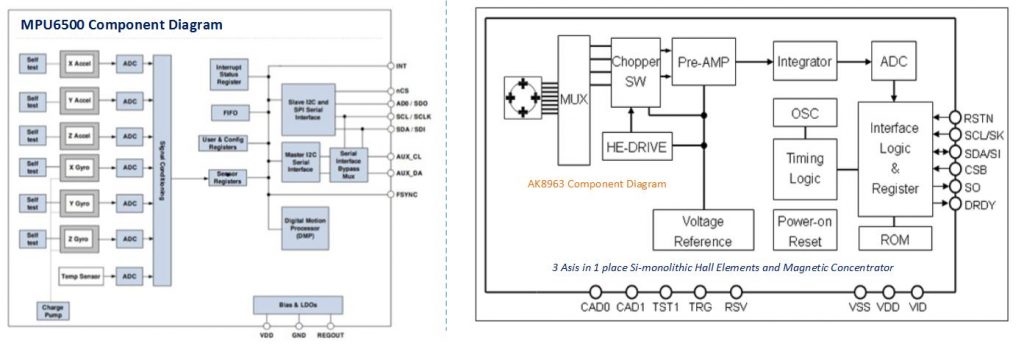
The MPU925 is a motion tracking device or MEMS (Micro Electro Mechanical System). A SIP (System in a Package) combining two components the MPU6500 & AK8963.
The MPU6500 which is contains 3 axis gyroscope, 3 axis accelerometer, and onboard digital motion processor (DMP) capable of processing complex sensor fusion algorithm from InvenSense. Please refer to the datasheet below for more information.
AK8963 is 3-AXIS electronic compass integrated circuit (IC) with high sensitive hall sensor technology on a small package. The AK8963 integrates magnetic sensor for detecting terrestrial magnetism in the X-AXIS, Y-AXIS, and Z-AXIS, a sensor driving circuit, signal amplifier chain, and arithmetic circuit for processing the signal from each sensor, it has self-test function integrated. This devise suitable for map heading in GPS equipment cellphone to realize pedestrian navigation function.
The MPU9250 sensor has an on-chip 1024 byte FIFO buffer and values are programmed to be placed in the FIFO buffer. Buffer will be read using Microcontroller or Arduino. The FIFO buffer will be used together with the interrupt signal, if the MPU9250 take place data into the FIFO buffer, it signals the MCU with the interrupt then the Arduino Knows that there is data into the FIFO buffer waiting to be read.
Sensor Fusion is a process which data from the several different sensor are FUSED to calculate something more than could be determined by any sensor alone or improve accuracy and reliability. On other words, it requires an estimation position and orientation on a dimensional space. A prerequisite for sensor fusion into calibration. The MPU itself it has to be calibrated and provide measurement in units. When using multiple sensor you need to calibrate in order to work well.
In this illustration we will going to wire the 3 type of sensors and each sensor has its own functionality and limitations.
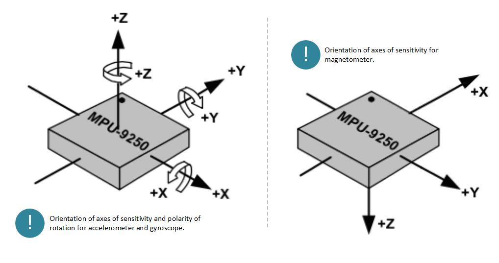
- ACCELEROMTER > X, Y, & Z linear axis motion sensing ( sensitive to vibration )
- GYROSCOPE > Pitch, Roll Yaw Rotational Sensing (Gyroscope Drift)
- MAGNETOMETER > X, Y, & Z axis magnetic field sensing (Sensitive to magnetic interface)
The gyroscope sense the orientation through angular velocity changes and therefore need to find the orientation, there is a tendency to drift over time because it only sense the changes and there is no fixed frame of reference.
Gyroscopic Drift or Null Drift Bias is an (Angular Velocity that represent as K * Vout) ω ≠ 0. This drift function changes with temperature and shows hysteresis.
Gyroscope is sensitive to gravity and vibration.
Accelerometer sense the changes in a direction with gravity which can orient a gyroscope to have more exact angular displacement. However, Accelerometers are more accurate in a static calculations when the system is reach to its fixed reference point of motion whereas the Gyroscope are good at detecting orientation when the system is in motion. Accelerometers tend to distort the acceleration due to external force as gravitational forces in motion which accumulates as noise at the system and error spikes on the output. With the addition of the accuracy of the Gyroscope merge with the accuracy of the accelerometer these sensor can be combined to avail more accurate orientation by utilizing the output of each sensor.
This device can be improved using special algorithms and filtering techniques, familiarizing more types of sensors and using them into correct error from one input to another to reduce the propagation error.
Required Components
- Arduino UNO,NANO,PRO,DUE,LEO, ESP8266, AVR
- MPU 9250 Breakout Board
- Jumper wires / DuPont Wires
- Solder less Breadboard
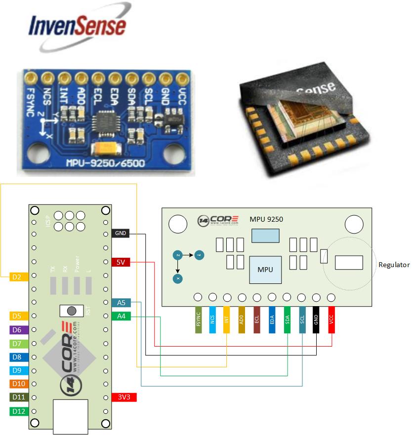
Wiring Diagram
Source Code / Sketch Code
|
1 2 3 4 5 6 7 8 9 10 11 12 13 14 15 16 17 18 19 20 21 22 23 24 25 26 27 28 29 30 31 32 33 34 35 36 37 38 39 40 41 42 43 44 45 46 47 48 49 50 51 52 53 54 55 56 57 58 59 60 61 62 63 64 65 66 67 68 69 70 71 72 73 74 75 76 77 78 79 80 81 82 83 84 85 86 87 88 89 90 91 92 93 94 95 96 97 98 99 100 101 102 103 104 |
/* ========================================================================= .:+osysso++:` `+yhs/-` `-+s+` `:/+++++++++` .:/++ooo++/-` .ooooooooooo+: :///////////- `odh/` `:y+` /ddhsooooooo+ /hddhsooooydddh sdddoooooosdddy` `////////////` -hds` `sy. +ddy` .ddd: sddy.dddo +ddd- .-----------` `hds :sssss/ -ossssso-yy` `hdd: oddy `ddd/oddd:......+dddo .++++++++++++ +dd` :sdddh` :ydddddddo +y/ .ddd+........ `hddy:.....:yddy.hdddddddddddy+. ```````````` ydy .hddd/+hdddhydddh/.+yo /hdddddddddd. :shddddddddhs/`+ddd:````-yddy- :ooooooooooo+ odh` sdddooyyyyyhddddyy.sy+ ` `......... ``.... ....` ```...` ` `` `` ` -dd+`::::` .:::- /yy. -oos+:-oos+--oos+: /o `+y o/: o:+/ h:`yos /+-`/+/+ s:y/y. /dd/ `+yy: +//+ +/:+ +/:+ -. `/ -:o.:/:`//+- + +:- :`-+:`://: +`o`+. -yds. `/yys- .`-.. .``` ```` .`` ` ` ``` ``-..` ` :ydy/.`````.-/oyhs: `+++oo+oo+:.+-++/-/ooo+o +:o/oo///:+/ .:oyhhhhhhhso:` `. ``` MPU9250 TEST CODE THE SOFTWARE IS PROVIDED "AS IS", WITHOUT WARRANTY OF ANY KIND, EXPRESS OR IMPLIED, INCLUDING BUT NOT LIMITED TO THE WARRANTIES OF MERCHANTABILITY, FITNESS FOR A PARTICULAR PURPOSE AND NONINFRINGEMENT. IN NO EVENT SHALL THE AUTHORS OR COPYRIGHT HOLDERS BE LIABLE FOR ANY CLAIM, DAMAGES OR OTHER LIABILITY, WHETHER IN AN ACTION OF CONTRACT, TORT OR OTHERWISE, ARISING FROM, OUT OF OR IN CONNECTION WITH THE SOFTWARE OR THE USE OR OTHER DEALINGS IN THE SOFTWARE. =========================================================================== */ // Arduino Wire library is required if I2Cdev I2CDEV_ARDUINO_WIRE implementation // is used in I2Cdev.h // i2Cdev library and MPU9250 must be installed as libraries, or else the .cpp/.h file // for both clsses must be in the inlcude path of your projects. #include "Wire.h" #include "I2Cdev.h" #include "MPU9250.h" // class default I2C address is 0x68 // specific I2C addresses may be passed as a parameter here // AD0 low = 0x68 (default for InvenSense evaluation board) // AD0 high = 0x69 MPU9250 accelgyro; int16_t ax, ay, az; int16_t gx, gy, gz; int16_t mx, my, mz; #define LED_PIN 13 //Define as pin 13 LED on Arduino Board bool blinkState = false; void setup() { // join I2C bus (I2Cdev library doesn't do this automatically) Wire.begin(); // initialize serial communication // (38400 chosen because it works as well at 8MHz as it does at 16MHz, but // it's really up to you depending on your project) Serial.begin(19200); //Initializing serial communication // initialize device Serial.println("14CORE | MPU9250 TEST CODE") Serial.println("Initializing I2C devices, please wait..."); accelgyro.initialize(); // verify connection Serial.println("Verifiying device connections..."); Serial.println(accelgyro.testConnection() ? "MPU9250 connection successful" : "MPU9250 connection failed"); // configure Arduino LED for pinMode(LED_PIN, OUTPUT); //Define as LED pin13 Output } void loop() { //Define as read raw Accelaration / Gyroscope measurement from the device. accelgyro.getMotion9(&ax, &ay, &az, &gx, &gy, &gz, &mx, &my, &mz); //these methods (and a few others) are also available //accelgyro.getAcceleration(&ax, &ay, &az); //accelgyro.getRotation(&gx, &gy, &gz); // display tab-separated accel/gyro x/y/z values Serial.print("a/g/m:\t"); Serial.print(ax); Serial.print("\t"); // Serial print AX Serial.print(ay); Serial.print("\t"); // Serial print AY Serial.print(az); Serial.print("\t"); // Serial print AZ Serial.print(gx); Serial.print("\t"); // Serial print GX Serial.print(gy); Serial.print("\t"); // Serial print GY Serial.print(gz); Serial.print("\t"); // Serial print GZ Serial.print(mx); Serial.print("\t"); // Serial print MX Serial.print(my); Serial.print("\t"); // Serial print MY Serial.println(mz); // Serial print MZ // blink LED to indicate activity blinkState = !blinkState; digitalWrite(LED_PIN, blinkState); } |
Download Datasheet & Code Libraries
- Download MPU9250 Registers | PDF
- Download MPU9250 Datasheet & Manual | PDF
- Download MPU9250 Libraries | Zip


This wiring diagram is WRONG! The 9250 is a 3.3V device, NOT 5V. Do NOT connect Vcc to 5V… it could destroy the device.
Some MPU 9250 immune to 5v. make it sure your board has LD1117, AMS1117, MCP1700 regulator. for safe usage use 3.3v.
tengo este error, use la ibreria q arriba aparece el link
‘class MPU9250’ has no member named ‘initialize’
Serial.println(“Initializing I2C devices, please wait…”);
accelgyro.initialize(); // in this part signal the error