In this illustration we will going to wire the CAN BUS (Controller Area Network Bus) Shield with Arduino, if you don’t have any background how CAN (Controller Area Network Bus) works please refer this this link. As you can see the illustration below it is demonstrated using ODB (On-board diagnostics) Interface as acquiring data from the car ECU (Engine Control Unit) if you don’t have any idea how ECU works please refer to this link
Modern vehicles are equipped with controller area network bus instead of placing a hundred, millions of cable wires communicating all devices that modern car has all electronic sensors, motors, relays lock doors, other things that plug into the car to enable more functions and having more features. From each node like the electric door locks, power window it is sending a message across the CAN when TIPM (Totally Integrated Power Module) detects a valid message it will react accordingly.
The CAN BUS Shield is a device driven by MCP2515 manufactured by Microchip Semiconductor, please refer to the MCP2515 Datasheet for more details.
Required Components
Arduino UNO
MCP2515 CAN BUS Shield
Jumper Wires / DuPont Wires
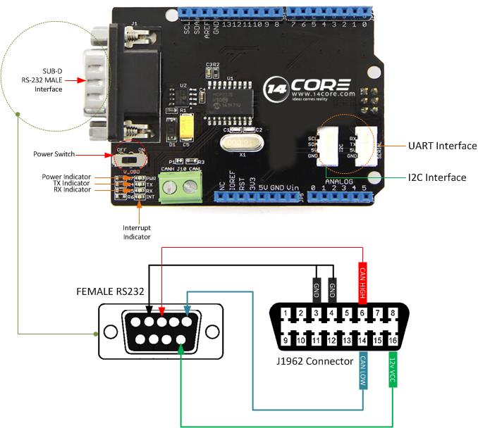
Wiring Diagram to OBD Interface
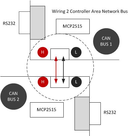
Wiring Diagram for 2 Controller Area Network
Arduino Sketch
Downloads
Download the CAN -Bus Shield Code Library | Pdf
Download the MCP2515 Datasheet | Pdf
Download the MCP2551 Datasheet | Pdf
Download the CAN Bus Shield Schematics Diagram | Pdf
Download the CAN Bus Shield Eagle File | Zip


