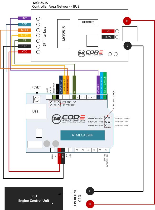
In this illustration we will going to wire the MCP2515 CAN BUS Breakout Module, MCP2515 is a standalone controller area network or CAN manufactured by Microchip semiconductor, that implements the CAN specification version 2.0B it is capable of transmitting and receiving both standard and extended data remote frames. These chip has two acceptance mask and six acceptance filter that are used to filter out unwanted messages, and reducing the host Microcontroller overhead, The MCP2515 chip has interface with microcontroller via an industry standard SPI (Serial Peripheral Interface). Please see the datasheet of MCP2515 below for your reference.

Introduction to CAN (Controller Area Network) Bus
A CAN BUS (Controller Area Network BUS is a standard design to allow the MCU (Microcontroller and device to talk each other in application without a host computer. It is actually a message based protocol designed for multiplex electrical wiring within, machinery, automobile and health facilities.
The MCP2515 Chip is a controller develop simplify applications that requires interfacing with a Can Bus. See the system implementation diagram using the device.
Required Components
- Arduino UNO, MEGA
- MCP2515 CAN BUS Module Board
- Jumper Wires / DuPont Wires
Optional
- OBD / OBD II Connector
- ECU (Engine Control Unit)
Wiring Diagram
Wiring to OBD Connector
Arduino Sketch
[crayon-690bd9fcb5ed0874116238/]
Downloads
Download CAN BUS Code Library | Zip
Download MCP2515 CAN BUS Datasheet | Pdf
Download MCP2515 Circuit Schematics | Pdf
