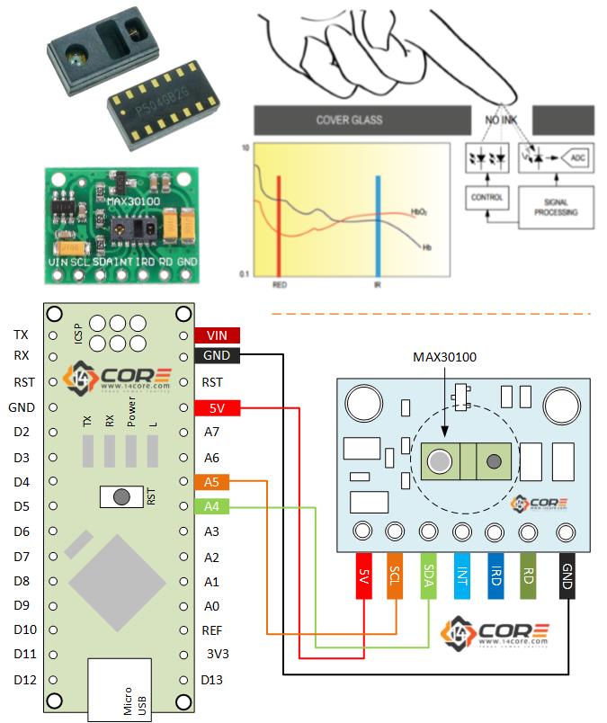
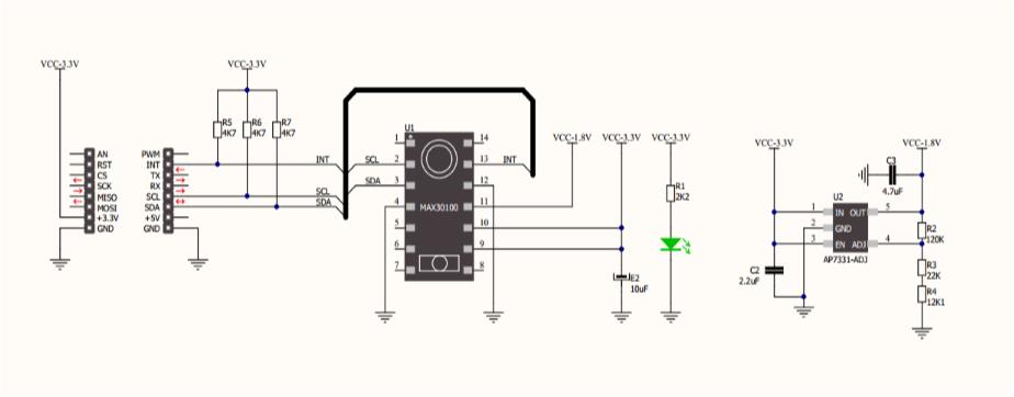
#include <MAX30100.h>
#include <MAX30100_BeatDetector.h>
#include <MAX30100_Filters.h>
#include <MAX30100_PulseOximeter.h>
#include <MAX30100_Registers.h>
#include <MAX30100_SpO2Calculator.h>
#include <Wire.h>
#define REPORTING_PERIOD_MS 500
/*
PulseOximeter is the higher level interface to the sensor
That offers:
> Beat Reporting
> Heart Pulse Rate Calculation
> SP02 OXIDATION LEVEL Calculation
*/
PulseOximeter pox;
const int numReadings=10;
float filterweight=0.5;
uint32_t tsLastReport = 0;
uint32_t last_beat=0;
int readIndex=0;
int average_beat=0;
int average_SpO2=0;
bool calculation_complete=false;
bool calculating=false;
bool initialized=false;
byte beat=0;
void onBeatDetected() //Calls back when pulse is detected
{
viewBeat();
last_beat=millis();
}
void viewBeat()
{
if (beat==0) {
Serial.print("_");
beat=1;
}
else
{
Serial.print("^");
beat=0;
}
}
void initial_display()
{
if (not initialized)
{
viewBeat();
Serial.print("14CORE | MAX30100 Pulse Oximeter Test");
Serial.println("--------------------------------------");
Serial.println("Place place your finger on the sensor");
Serial.println("--------------------------------------"); ;
initialized=true;
}
}
void display_calculating(int j){
viewBeat();
Serial.println("Measuring");
for (int i=0;i<=j;i++) {
Serial.print(". ");
}
}
void display_values()
{
Serial.print(average_beat);
Serial.print("| Bpm ");
Serial.print("| SpO2 ");
Serial.print(average_SpO2);
Serial.print("%");
}
void calculate_average(int beat, int SpO2)
{
if (readIndex==numReadings) {
calculation_complete=true;
calculating=false;
initialized=false;
readIndex=0;
display_values();
}
if (not calculation_complete and beat>30 and beat<220 and SpO2>50) {
average_beat = filterweight * (beat) + (1 - filterweight ) * average_beat;
average_SpO2 = filterweight * (SpO2) + (1 - filterweight ) * average_SpO2;
readIndex++;
display_calculating(readIndex);
}
}
void setup()
{
Serial.begin(115200);
pox.begin();
pox.setOnBeatDetectedCallback(onBeatDetected);
}
// Make it sure that you need to call update as fast as possible
void loop()
{
pox.update();
if ((millis() - tsLastReport > REPORTING_PERIOD_MS) and (not calculation_complete)) {
calculate_average(pox.getHeartRate(),pox.getSpO2());
tsLastReport = millis();
}
if ((millis()-last_beat>10000)) {
calculation_complete=false;
average_beat=0;
average_SpO2=0;
initial_display();
}
}


We tried to use this code. It worked the first time, displaying the bpm and SO2 %. However, if we leave our finger the sensor, the code will not display another bpm or SO2 %, it will only spit out “^-^-….” continuously.
You need to place a function inside the loop that reads the sensor input value contentiously.
Hi, how to add it please? I am total beginer and this is my first project – using Arduino Lilypad and have same trouble – show me this:
_^_^Measuring
. . _Measuring
. . . ^Measuring
. . . . _Measuring
. . . . . ^_^_^_^_^_
I try with Nodemcu 12E, i use same connection but it dosenot work for me, can you help
Use this library > https://www.14core.com/wp-content/uploads/2017/08/MAX30100.zip
How can I add firebase realtime database connection code in this code plz plz
This is the code library for Firebase API call for Arduino
Follow this link just download and extract example code also available.
> https://www.14core.com/wp-content/uploads/2022/07/firebase-arduino-master.zip