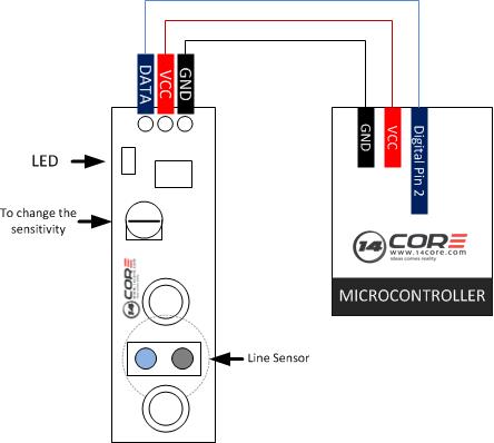
In this illustration we will going to wire the Line Finder Sensor Module HCARDUXXXX5. This module requires only DIO pin defined as an input) to work. When the sensor detects a dark line it will trigger the signal into HIGH, if its LIGH then it will trigger as LOW. This module is the characteristics on the previous article the Obstacle Avoidance Sensor Module. This module is perfect for line following robot.
Required Components
Arduino UNO/MEGA/MINI/PRO/LEO
Line finder sensor module board
Solder Less Breadboard
Jumper Wire
Wiring Diagram
Arduino Sketch Code
1 2 3 4 5 6 7 8 9 10 11 12 13 14 15 16 17 18 19 20 21 22 23 24 25 26 |
/*__________________________________________________________ $$$$$$$$$$$$$$$$$$$$$$$$$$$$$$$$$$$$$$$$$$$$$$$$$$$$$$$$$$$$ 14CORE.com ARDUINO LINE FINDER MODULE $$$$$$$$$$$$$$$$$$$$$$$$$$$$$$$$$$$$$$$$$$$$$$$$$$$$$$$$$$$$ ____________________________________________________________ */ #define LineFinder 2 //Define as the Arduino Digital Pin 2 void setup() // Initializing Input Operation { Serial.begin(9600); //start serial port for displaying the status of the sensor in baurd rate 9600 pinMode(LineFinder, INPUT); //Configure the Input Operation pin in the sensor will be connected to as an input } void loop() /* program loop */ { if (!digitalRead(LineFinder)) // If the board detect an object it will pulled as low. Serial.println("14CORE> Line detected !"); delay(200); //Delay at 2 seconds then ready to read again. } |
Wiring the Line finder Sensor with Arduino