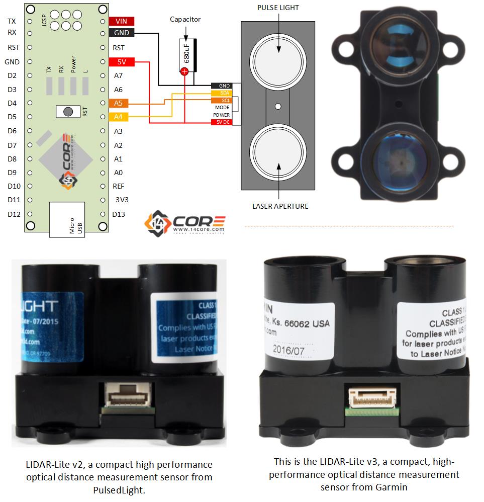
This is another illustration that demonstrate how to wire the LIDAR Sensor on your Microcontroller. LIDAR (Light Detection and Ranging) is a remote sensing device which is capable capture geographical information. LIDAR data is often collected by the survey of aircraft or ground vehicle. NOAA scientist use LIDAR devices to examine both natural and man-made environment. LIDAR Data supports activities such as inundation, storm surge modeling, hydrodynamic modeling, shoreline mapping, emergency response, hydro-graphic surveying, coastal vulnerability analysis. LIDAR also use in self-driving cars and advance robotics.
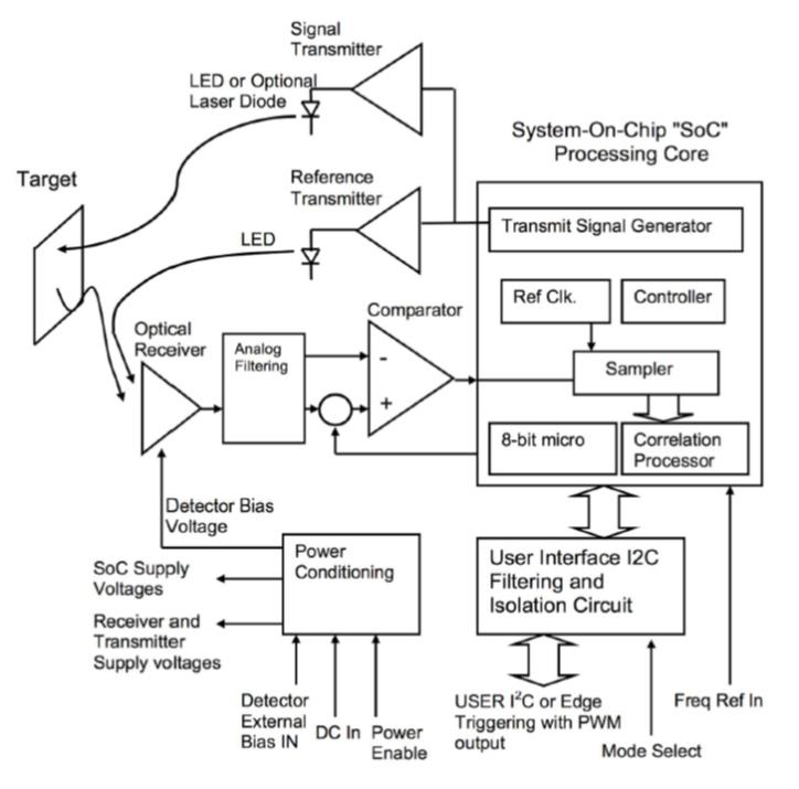
Block Diagram
- Power : 4.7 ~ 5.5 DC Nominal, Maximum 6V DC
- Current Consumption <2mA @ 1 Hz (Shutdown between measurements), < 100mA (Continuous Operation)
- Max Operating Temp: 70 Degree Celsius
- External Trigger 3.3v Logic, HIGH/LOW Triggered
- PWM Range Output: PWM Signal proportional Range, 1 msec/meter, 10 usec step size
- i2c Machine Interface: 100Kb – Fixed, 0xC4 slave address. Internal register access and control.
- Support i2C Command: Single distance measurement, velocity, signal strength
- Mode Control: Busy Status i2C, External Trigger Input / PWM Output
- Max Range Under Typical Conditions: ~ 40m
- Accuracy: +/-2.5cm, +/- ~1″
- Default Rep Rate: ~50 Hz
On illustration we are going to wire the LIDAR-Lite by pulsedlight3d & Garmin a low cost LIDAR that can be used in Automotive Blind-spot sensing, traffic monitoring, 3D image scanning, collision avoidance, industrial level measurement, security system components, medical imaging, aerospace. The LIDAR-Lite is using i2C serial communication bus, easily to communicate with your SBMC (Single Board Micro Computer) or in your MCU (Microcontroller). LIDAR-Lite can be connected as slave under the control of the master i2c. It supports standard 100 kHz data transfer mode, and it has 7bit slave address with a default value of 0x62 HEX notation. The effective 8bit address is OxC4 write, OxC5 read. Please refer the official datasheet can be download below.
Required Components
- Arduino Microcontroller, Teensy (Teensy Duino), ATMEGA328 16/12, ATMEGA32u4 16/8/ MHz, ESP8266, ATMEGA250 16 MHz, ATSAM3x8E, ATSAM21D, ATTINY85 16/8 MHz (Note: The Diagram below is using NANO. If your using other MCU please refer to the respective pin-outs diagram)
- LIDAR – V1 / LIDAR – V2 / LIDAR – V3
- Capacitor (680UF)
- Resistor (1K)
- Jumper Wire / DuPont Wire
- Solder Less Bread Board
i2C Wiring Guide
PWM / Continuous Mode Wiring Diagram
i2C Source Code
[crayon-6816e607009a5545401287/]
PWM Source Code
[crayon-6816e607009ad559380360/]
Continuous Mode Source Code
[crayon-6816e607009b2931920776/]
Downloads
- Download i2C Library | Zip
- Download LIDAR Datasheet Version 1| PDF
- Download LIDAR Datasheet Version 2| PDF
- Download LIDAR Datasheet Version 3 | PDF

