In this illustration we will going to wire the Infrared Transmitter. The infrared transmitter are now common in our house, offices, even in our cars and other places, etc., It is based on wireless sensing, but also can be more a remote control.
Infrared emission control also known as infrared emitting diode, actually it’s belongs to two tube can be directly converted into electrical energy near-infrared light and a light emitting device can radiate out, its structure with the general principle of the light and the emitting diode similar with the semiconductor on the different components. The infrared communication has its two parts or two elements, mainly composed of silicon crystal and highly integrated circuits, the main function is to filter, shaping, decoding, zoom and other functions, that Photodiode (PD) is the responsible to receive the optical signal by number.
The illustrated schematics below works as modulated infrared emitting diode, can transmit after receiving, decoding, filtering, and a series of operations after the signal recovery.
The infrared emitting diodes should be clean and good conditions and during the operation must not exceed the limit value of positive to the current 30~60 mA, pulse forward current 0.3 to 1 A, Reverse voltage 5v, power dissipation 92 mW, working temperature upto 260 degree Celsius. The infrared emission tube and then closed head should be paired, otherwise it will distract the sensitivity.
The infrared receiver is a low humidity environment storage keep in mind to protect the infrared receiver surface, do not touch the surface, do not wash or polluting gas in body or salt environment, place it without external pressure.
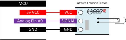
As you can see the illustration below to understand the infrared transmitter and receiver module specific connection with the Arduino. We will going to test the receiving and transmitting base on two Arduino Board. A master or a transmitter and the slave.

Required Components
Arduino Boards
Infrared Emission Sensor Module
Solder less bread board
Jumper / DuPont Wires
Wiring Diagram
Arduino Sketch Code


