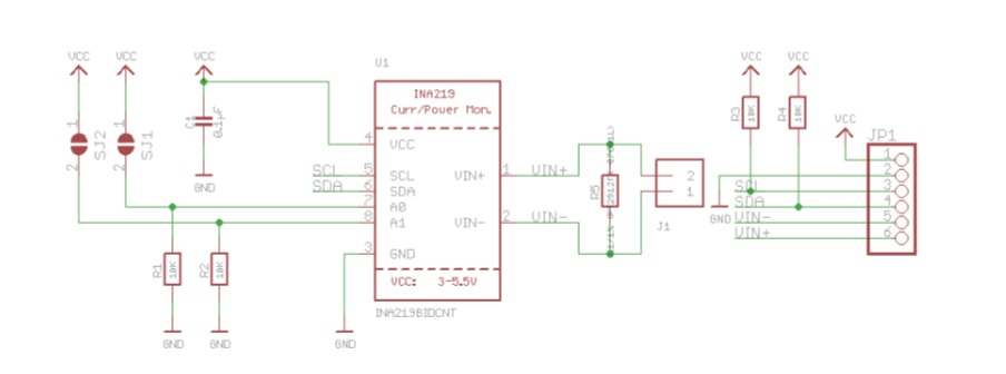
This is the INA219B breakout module to measure both high side voltage and DC current draw over i2C with 1 percent precision. Current measuring devices such as current panel meter are good only for low side measuring it means that unless you’re going to integrate a battery or placing a measuring resistor between the target ground and main ground. This will cause a problem within the circuits since electronics will not accept when the ground references change and move with varying current draw.
The INA219B is much smarter it can handle high side of the current measuring up to +26V DC, even though it is powered with 3v or 5v it will also notify back the high side of the voltage. Which is excellent for tracking battery life.
Specification
- 0.1 ohm 1% 2 watts Current Sense Resistor
- Up to +26 Volts Target Voltage
- Up to ±3.2 Amp Current Measurement with ± 0.8mA resolution
- I2C 7bit addresses 0x40, 0x41, 0x44, 0x45
Required Components
- Arduino Microcontroller, Tenssy (Tenssyduino Integrated), ESP8266 NodeMCU (Arduino IDE Integrated)
- INA219 Breakout Module I2C 7bit addresses 0x40, 0x41, 0x44, 0x45 (See the jumper settings)
- Jumper Wires / DuPont Wires
- Solder Less Breadboard
- LCD Screen 16×2 Driven I2C (Refer to i2C address – OPTIONAL)
Schematics Diagram
Wiring Diagram
Source Code
|
1 2 3 4 5 6 7 8 9 10 11 12 13 14 15 16 17 18 19 20 21 22 23 24 25 26 27 28 29 30 31 32 33 34 35 36 37 38 39 40 41 42 43 44 45 46 47 48 49 50 51 52 |
#include <Wire.h> #include <INA219.h> INA219 ina219; #if defined(ARDUINO_ARCH_SAMD) // for Zero, output on USB Serial console, remove line below if using programming port to program the Zero! #define Serial SerialUSB #endif void setup(void) { #ifndef ESP8266 while (!Serial); // will pause Zero, Leonardo, etc until serial console opens #endif uint32_t currentFrequency; Serial.begin(115200); Serial.println("14CORE | Get Current Test "); // Initialize the INA219. // By default the initialization will use the largest range (32V, 2A). However // you can call a setCalibration function to change this range (see comments). ina219.begin(); // To use a slightly lower 32V, 1A range (higher precision on amps): //ina219.setCalibration_32V_1A(); // Or to use a lower 16V, 400mA range (higher precision on volts and amps): //ina219.setCalibration_16V_400mA(); Serial.println("Measuring voltage and current with INA219 ..."); } void loop(void) { float shuntvoltage = 0; float busvoltage = 0; float current_mA = 0; float loadvoltage = 0; shuntvoltage = ina219.getShuntVoltage_mV(); busvoltage = ina219.getBusVoltage_V(); current_mA = ina219.getCurrent_mA(); loadvoltage = busvoltage + (shuntvoltage / 1000); Serial.print("Bus Voltage: "); Serial.print(busvoltage); Serial.println(" V"); Serial.print("Shunt Voltage: "); Serial.print(shuntvoltage); Serial.println(" mV"); Serial.print("Load Voltage: "); Serial.print(loadvoltage); Serial.println(" V"); Serial.print("Current: "); Serial.print(current_mA); Serial.println(" mA"); Serial.println(""); delay(2000); } |
Downloads


There are 4 separate batteries connected to your circuit. Can I connect 4 consecutively connected batteries? Nothing will burn in this case?
NA219 has it’s integrated isolator..
Can you give a source code valid for the four sensors setup visible on this page?
Just a note to report that the INA219 Code Library link seems to be directed to the PDF datasheet. Can you fix it? Thank you :-)
Code library has been updated..
How can I change the value of the shunt?