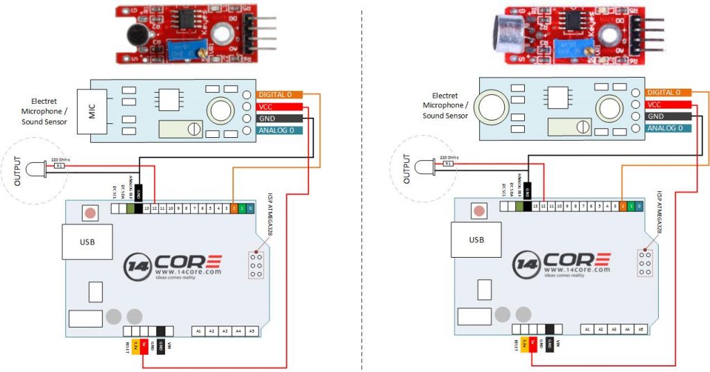
This is a breakout board of an Electret microphone, sound sensor. Which is essentially provide your Microcontroller an ear to detect or listen sound wave. This microphone has 100Hz-10kHz with an 60x mic preamplifier to amplify the sounds of voice, claps, door knocks or any sounds loud enough to detected by the microcontrollers. This device use uses analog or digital as the connected either digital or analog. Basically the electret Mic translate amplitude not volume by capturing sound wave between two conducting rod or plates one is the vibrating diaphragm and the other one fixed in the microphone and converting them into electrical waves form . These electrical signals are amplified and pickup by the microcontroller. As you can see below there are two example one is using digital and the other is using analog. Just follow the illustration below for the wiring.
Required Components
- Arduino UNO, MEGA, DUE, LEO, NANO, PRO, ESP8266 13, 12, 7, 11.
- LED (Any Color)
- Resistor 200 Ohms
- Solder Less Bread Board
- Jumper Wire / DuPont Wire
Wiring Diagram for Digital
Source Code / Sketch Code for Digital Pin
Wiring Diagram for Analog
Source Code / Sketch Code for Analog Pin
Example Code for Sound Detection with PWM


