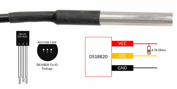
In this illustration we will going to wire the DS18B20 single wire temperature sensor. The digital DS18B20 Sensor provide fairly good accuracy and range of connection. The wire length can be reach up to 100m. The DS18B20 has four main data connection.
1. 64bit layered ROM
2. Temperature Sensor
3. Nonvolatile Temperature Alarm Trigger TH & TL
4. A configurable Register
These device derives its power from the 1 wire communication line by storing energy on an internal capacitor during the periods of time when the signal line is HIGH and continues to operate off this power source during the LOW times of the 1 wire line until it returns HIGH to replenish the capacitor supply. As an alternative, the DS18B20 may also be powered from an external 3v~5.5v supply.
The DS18B20 communication is using 1 wire port. With the 1wire port the memory and control functions will not be available before the ROM function protocol has been established. The master must first provide on of five ROM function command.
1. READ ROM
2. MATCH ROOM
3. SEARCH ROM
4. SKIP ROM
5. ALARM SEARCH
These commands operate on the 64bit lasered ROM portion each device and the single out a specific device if many are preset on the 1-wire line as well as indicate to the BUS master how many and what types of devices are present. After a ROM function sequence has been successfully executed, the memory and control function are accessible and the master may then provide any one of the six memory and control function commands.
One control function command instructs the DS18B20 to perform a temperature measurement. The result of this measurement. Will be placed in the DS18B20 scratchpad memory, and may be read by issuing a memory function command which reads the contents of the scratchpad memory. The temperature alarm triggers TH and TL consist of 1 byte EEPROM each. If the alarm search command is not applied to the DS18B20, these registers may be used as a general purpose user memory. The scratchpad also contains a configuration byte to set the desired resolution of the temperature to digital conversion. Writing TH, TL, and the configuration byte is done using a memory function command. Read access to these register is through the scratchpad. All data is read and written least significant bit first.
Above block diagram is shows the circuitry. This circuitry steals power whenever the DQ or Vdd Pins are high. DQ will provide sufficient power as long as the specified timing and voltage requirements are met. The advantages of parasite power are.
Using parasiting off this pin, no local power source is needed for remote sensing of temperature.
The ROM may be read in absence of normal power in order for the DS18B20 to be able to perform accurate temperature conversions, sufficient power must be provide over the DQ line when a temperature conversion is taking place. Since the operating current of the DS18B20 is up to 1.5mA, the DQ line will not have sufficient drive due to the 5k pull-up resistor.
This problem is particularly acute if several DS18B20 are on the same DQ and attempting to convert simultaneously. There are two ways to assure that the DS18B20 has sufficient supply current during its active conversion cycle.
Provide a strong pullup on the DQ line whenever temperature conversion or copies to the E2 memory are taking place. This may be accomplished by using a MOSFET to pull the DQ line directly to the power supply.
The DQ line must be switched over to the strong pull-up within 10u maximum after issuing any protocol that involves copying the E2 memory or initiates temperature conversion. When using the parasite power mode, the V pin must be tied to the ground.
Wiring Requirements
Arduino Board
DS18B20 Temperature Sensor
1x 4.7k Ohms Resistor
LCD i2C LCD 16×2 or 5110 LCD (Optional)
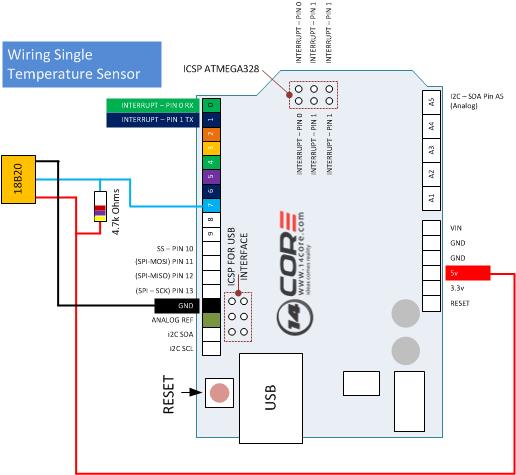
Wiring Single DS18B20 Diagram Schematics
Wiring Single DS18B20 Wired Diagram Schematics
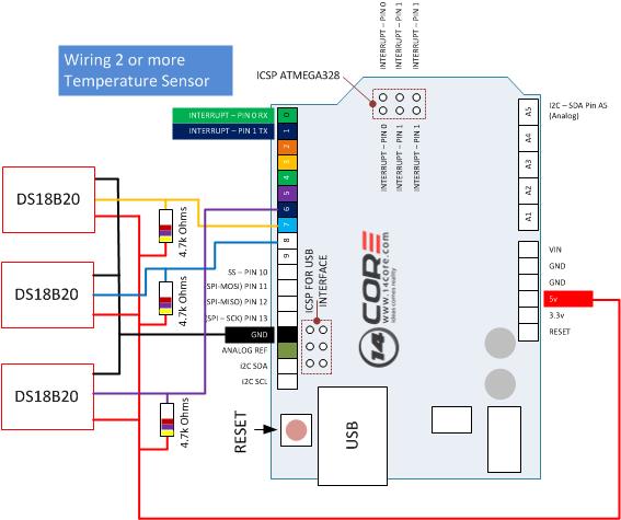
Wiring Multiple DS18B20 Diagram Schematics
Arduino Sketch without LCD Display
1
2
3
4
5
6
7
8
9
10
11
12
13
14
15
16
17
18
19
20
21
22
23
24
25
26
27
28
29
30
31
32
33
34
35
36
37
38
39
40
41
42
43
44
45
46
47
48
49
50
51
52
53
54
55
56
57
58
59
60
61
62
63
64
65
66
#include <OneWire.h>
intDS18S20_Pin=7;//DS18S20 Signal pin on digital 7
//Temperature chip i/o
OneWire ds(DS18S20_Pin);// on digital pin 7
voidsetup(void){
Serial.begin(9600);//Start Serial Communication Baud Rate 9600
}
voidloop(void){
floattemperature=getTemp();
Serial.println(temperature);
delay(100);//just here to slow down the output so it is easier to read
}
floatgetTemp(){
//returns the temperature from one DS18S20 in DEG Celsius
bytedata[12];
byteaddr[8];
if(!ds.search(addr)){
//no more sensors on chain, reset search
ds.reset_search();
return-1000;
}
if(OneWire::crc8(addr,7)!=addr[7]){
Serial.println("CRC is not valid!");
return-1000;
}
if(addr[0]!=0x10&&addr[0]!=0x28){
Serial.print("Device is not recognized");
return-1000;
}
ds.reset();
ds.select(addr);
ds.write(0x44,1);// start conversion, with parasite power on at the end
14CORE LCD 16x2 DS18B20 Temperature Sensor Test Code
www.14core.com
*/
#include <LiquidCrystal_I2C.h>
#include <Wire.h>
#include <SoftwareSerial.h>
#include <OneWire.h>
#define BACKLIGHT_PIN 3
#define En_pin 2
#define Rw_pin 1
#define Rs_pin 0
#define D4_pin 4
#define D5_pin 5
#define D6_pin 6
#define D7_pin 7
LiquidCrystal_I2C lcd(0x27,20,4);
OneWire ds(7);
bytei;
bytepresent=0;
bytetype_s;
bytedata[12];
byteaddr[7];
floatcelsius;
voidsetup(){
lcd.init();
lcd.init();
lcd.setBacklight(HIGH);
lcd.home();
lcd.setCursor(0,0);
lcd.print("14CORE-Temperture Test Code");
lcd.setCursor(0,1);
lcd.print("<<initializing>>>");
if(!ds.search(addr))
{
lcd.print("No more addr...");
ds.reset_search();
delay(1000);
return;
}
if(OneWire::crc8(addr,7)!=addr[7])
{
lcd.print("CRC error!");
delay(1000);
return;
}
// the first ROM byte indicates which chip
switch(addr[0]){
case0x10:
lcd.print("Chip = DS18S20");// or old DS1820
type_s=1;
break;
case0x28:
lcd.print("Chip = DS18B20");
type_s=0;
break;
case0x22:
lcd.print("Chip = DS1822");
type_s=0;
break;
default:
lcd.print("Unknown device.");
return;
}
delay(2000);
lcd.setCursor(0,1);
lcd.print(" ");
}
voidloop()
{
lcd.setCursor(0,1);
ds.reset();
ds.select(addr);
ds.write(0x44,1);// start conversion, with parasite power on at the end
delay(1000);// maybe 750ms is enough, maybe not
present=ds.reset();
ds.select(addr);
ds.write(0xBE);// Read Scratchpad
for(i=0;i<9;i++){// we need 9 bytes
data[i]=ds.read();
}
/* Convert the data to actual temperature because the result is a 16 bit signed integer, it should be stored to an "int16_t" type, which is always 16 bits even when compiled on a 32 bit processor. */
int16_t raw=(data[1]<<8)|data[0];
if(type_s){
raw=raw<<3;// 9 bit resolution default
if(data[7]==0x10){
// "count remain" gives full 12 bit resolution
raw=(raw&0xFFF0)+12-data[6];
}
}else{
bytecfg=(data[4]&0x60);
// at lower res, the low bits are undefined, so let's zero them
if(cfg==0x00)raw=raw&~7;// 9 bit resolution, 93.75 ms
elseif(cfg==0x20)raw=raw&~3;// 10 bit res, 187.5 ms
elseif(cfg==0x40)raw=raw&~1;// 11 bit res, 375 ms
//default is 12 bit resolution, 750 ms conversion time
}
celsius=(float)raw/16.0;
lcd.print("T=");
lcd.print(celsius);
lcd.print("C");
}
LCD 16×2 with I2C Driver
1
2
3
4
5
6
7
8
9
10
11
12
13
14
15
16
17
18
19
20
21
22
23
24
25
26
27
28
29
30
31
32
33
34
35
36
37
38
39
40
41
42
43
44
45
46
47
48
49
50
51
52
53
54
55
56
57
58
59
60
61
62
63
64
65
66
67
68
69
70
71
72
73
74
75
76
77
78
79
80
81
82
83
84
85
86
87
88
89
90
91
92
93
94
95
96
97
98
99
100
101
102
103
104
105
106
/*
14CORE LCD 16x2 DS18B20 Temperature Sensor Test Code
www.14core.com
*/
#include <LiquidCrystal_I2C.h>
#include <Wire.h>
#include <SoftwareSerial.h>
#include <OneWire.h>
#define BACKLIGHT_PIN 3
LiquidCrystal_I2C lcd(0x3F,2,1,0,4,5,6,7,3,POSITIVE);//Note: Mostly use address is 0x27, 0x3f, 0x38
OneWire ds(7);
bytei;
bytepresent=0;
bytetype_s;
bytedata[12];
byteaddr[7];
floatcelsius;
voidsetup(){
//lcd.home ();
lcd.begin(16,2);
lcd.setCursor(0,0);
lcd.print("14CORE / TEMP");
lcd.setCursor(0,1);
if(!ds.search(addr))
{
lcd.print("No more addr...");
ds.reset_search();
delay(1000);
return;
}
if(OneWire::crc8(addr,7)!=addr[7])
{
lcd.print("CRC error!");
delay(1000);
return;
}
// the first ROM byte indicates which chip
switch(addr[0]){
case0x10:
lcd.print("Chip = DS18S20");// or old DS1820
type_s=1;
break;
case0x28:
lcd.print("Chip = DS18B20");
type_s=0;
break;
case0x22:
lcd.print("Chip = DS1822");
type_s=0;
break;
default:
lcd.print("Unknown device.");
return;
}
delay(2000);
lcd.setCursor(0,1);
lcd.print(" ");
}
voidloop()
{
lcd.setCursor(0,1);
ds.reset();
ds.select(addr);
ds.write(0x44,1);// start conversion, with parasite power on at the end
delay(1000);// maybe 750ms is enough, maybe not
present=ds.reset();
ds.select(addr);
ds.write(0xBE);// Read Scratchpad
for(i=0;i<9;i++){// we need 9 bytes
data[i]=ds.read();
}
/* Convert the data to actual temperature because the result is a 16 bit signed integer, it should be stored to an "int16_t" type, which is always 16 bits even when compiled on a 32 bit processor. */
int16_t raw=(data[1]<<8)|data[0];
if(type_s){
raw=raw<<3;// 9 bit resolution default
if(data[7]==0x10){
// "count remain" gives full 12 bit resolution
raw=(raw&0xFFF0)+12-data[6];
}
}else{
bytecfg=(data[4]&0x60);
// at lower res, the low bits are undefined, so let's zero them
if(cfg==0x00)raw=raw&~7;// 9 bit resolution, 93.75 ms
elseif(cfg==0x20)raw=raw&~3;// 10 bit res, 187.5 ms
elseif(cfg==0x40)raw=raw&~1;// 11 bit res, 375 ms
//default is 12 bit resolution, 750 ms conversion time
We use cookie to provide you the best possible experience, this site uses cookies and by continuing to use the site you agree that we can save them on your device. Cookies are small text files which are placed on your computer and which remember your preference / some details of your visit. Our cookies don’t collect any personal information. For information, please read our Privacy Statement and Cookie Policy , which also explains how to disable this option in your browser. Cookie SettingsACCEPT
Privacy & Cookies Policy
Privacy Overview
This website uses cookies to improve your experience while you navigate through the website. Out of these cookies, the cookies that are categorized as necessary are stored on your browser as they are as essential for the working of basic functionalit...
Necessary cookies are absolutely essential for the website to function properly. This category only includes cookies that ensures basic functionalities and security features of the website. These cookies do not store any personal information.
Any cookies that may not be particularly necessary for the website to function and is used specifically to collect user personal data via analytics, ads, other embedded contents are termed as non-necessary cookies. It is mandatory to procure user consent prior to running these cookies on your website.