The APDS9253 001 is a digital RGB IR Flux Sensor, and an ambient light sensor that converts light intensity to a digital output signal, The APDS9253 sensor uses 4 individual channels of RGB (Red, Green, Blue and Infrared (RGB+IR) suitable for designing a matrix arrangement. Additionally, it allows the device to have an optimal angular response and accurate RGB spectral response with high LUX accuracy over various light sources. This device communicates up to 400kHz using TWI (Two Wire Interface) or i2C protocol interface and integrated programmable interrupt controller that takes minimal resource from the microcontroller.
The color sensing technology is useful in an application such as LED RGB backlight controller, solid-state lightning, reflected LED color sampler, fluorescent light color temperature detection, applicable for Smart Handheld Devices, Detections of ambient light to control display backlighting, wearable devices, computing devices, consumer devices, automatic residential and commercial lighting management, lab instrumentation’s, etc. with the help of IR sensing the device can be used to read the IR content in certain lighting conditions and detect the type of light source.
The APDS9253001 has an advance accuracy of correlated color temperature (CCT) with approximate human eye response with a green channel and low light sensitivity that operates behind darkened glass at 50 Hz / 60 Hz light flicker immunity.
This sensor powered by 1.7v to 3.6v with a power management capability at low active current and low standby current for more technical details and product information please refer to the documentation below.

Requirements and Alternatives
- Arduino IDE | Atmel Studio | MPLAB | Energia | PlatformIO | Processing |
- Eclipse IDE | embedXcode | Ktechlab | Codebender | Visual Micro | Zeus IDE
- SONY SPRESENSE Development Board
- Please refer to this link
- ESPRESSIF
- ESP8266 12, 12E, ESP32, ESP8266 NodeMCU, ESPDuino
- Microchip
- ATMEGA4809 Curiosity Nano, ChipKIT DP32, chipKIT WF32,
- ARDUINO
- MKR WAN, MK, MKR, PRO, FIO, NANO, EVERY, UNO, MINI, MEGA, PRO MINI, LEO, BT, DUE, ETHERNET,LILYPAD, ATMEGA328 16/12, ATMEGA32u4 16/8/ MHz, ESP8266,ATMEGA250 16 MHz, ATSAM3x8E, STM32,
- Note: For AVR (please see the flash size of the MCU and respective pin-outs & bus configuration )
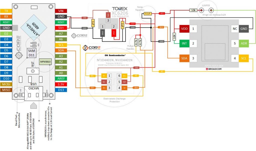
- Note: The Diagram below is using ATMEGA328TQFP & ATMEGA4809. (please refer to each MCU’s respective pin-outs & bus configuration)
- Others
- Teensy, MSP430 Launchpad, Flora, Metro MCU, Trinket, Pro Trinket, LinkItOne, Seeeduino XIAO.
- Broadcom APDS 9253 001 RGB Light Sensor
- XC6206 3.0 Regulator / AMS1117 3.3v Regulator
- NTJD4401N Dual N-Channel MOSFET
- Resistors (See below required values)
- Capacitor(See below required values)
Wiring Guide
Source Code
|
1 2 3 4 5 6 7 8 9 10 11 12 13 14 15 16 17 18 19 20 21 22 23 24 25 26 27 28 29 30 31 32 33 34 35 36 37 38 39 40 41 42 43 44 45 46 47 48 49 50 51 52 53 54 55 56 57 58 59 60 61 62 63 64 65 66 67 |
#include "Wire.h" #include <APDS9301_Library.h> APDS9301 apds; #define INT_PIN 2 // We'll connect the INT pin from our sensor to the // INT0 interrupt pin on the Arduino. bool lightIntHappened = false; // flag set in the interrupt to let the // mainline code know that an interrupt occurred. void setup() { delay(1000); Serial.println("14CORE | TEST CODE FOR >>>"); Serial.println("======== APDS9301 ========"); delay(1000); Serial.println("Initializing.............."); delay(2000); delay(5); // The CCS811 wants a brief delay after startup. Serial.begin(115200); Wire.begin(); // APDS9301 sensor setup. apds.begin(0x39); // We're assuming you haven't changed the I2C apds.setGain(APDS9301::LOW_GAIN); // Set the gain to low. Strictly apds.setIntegrationTime(APDS9301::INT_TIME_13_7_MS); // Set the apds.setLowThreshold(0); // Sets the low threshold to 0, effectively apds.setHighThreshold(50); // Sets the high threshold to 500. This apds.setCyclesForInterrupt(1); // A single reading in the threshold apds.enableInterrupt(APDS9301::INT_ON); // Enable the interrupt. apds.clearIntFlag(); // Interrupt setup pinMode(INT_PIN, INPUT_PULLUP); // This pin must be a pullup or have // a pullup resistor on it as the interrupt is a // negative going open-collector type output. attachInterrupt(digitalPinToInterrupt(INT_PIN), lightInt, FALLING); Serial.println(apds.getLowThreshold()); Serial.println(apds.getHighThreshold()); } void loop() { static unsigned long outLoopTimer = 0; apds.clearIntFlag(); // This is a once-per-second timer that calculates and prints off // the current lux reading. if (millis() - outLoopTimer >= 1000) { outLoopTimer = millis(); Serial.print(">>>>>> Luminous flux: "); Serial.println(apds.readCH0Level(), 6); if (lightIntHappened) { Serial.println(">>>>> Interrupt"); lightIntHappened = false; } } } void lightInt() { lightIntHappened = true; } |


