


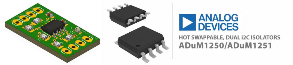
This is ADuM1250 is a digital isolator product manufactured by Analog Devices. It uses a technology called iCoupler to provide electrical isolation between the input and output side of the device, while preserving the digital signal. The ADuM1250 can be used in a variety of applications, including data and signal isolation in power electronics, industrial control systems, and medical equipment. ADuM1250 works by using Analog Devices’ iCoupler technology, which is a chip-scale transformer-based digital isolator. The iCoupler technology uses magnetic coupling between multiple micro-transformers to transmit digital signals across the isolation barrier, thereby preserving the signal integrity and providing electrical isolation.

The ADuM1250 receives the input signal, which is then transformed into a high-frequency signal using a pulse width modulation (PWM) technique. This high-frequency signal is transmitted across the isolation barrier using the iCoupler technology, and then reconverted into the original digital signal at the output side. In this way, the ADuM1250 provides both electrical isolation and signal transmission while maintaining signal integrity, making it suitable for use in a wide range of applications due to its ability to provide electrical isolation while preserving the digital signal. Some of the best applications for the ADuM1250 include:
- Industrial control systems: In industrial control systems, the ADuM1250 can be used to isolate control signals from high-voltage or high-current portions of the system.
- Power electronics: In power electronics, the ADuM1250 can be used to isolate control signals and data from the high-voltage DC or AC power signals.
- Medical equipment: In medical equipment, the ADuM1250 can be used to isolate patient signals and control signals to ensure patient safety.
- Automation systems: In automation systems, the ADuM1250 can be used to isolate control signals and data from high-voltage or high-current portions of the system.
- Renewable energy systems: In renewable energy systems, such as solar power inverters, the ADuM1250 can be used to isolate control signals and data from the high-voltage DC power signals.
These are some of the best applications for the ADuM1250, but the device can be used in many other applications where electrical isolation and signal preservation are required.
How the Hot Swappable i2C Works?
Hot swappable dual I2C isolators are electrical components that isolate two I2C bus segments, allowing for hot-swapping or changing of devices on the bus without disrupting the communication between other devices. They provide electrical isolation, which helps prevent ground loops and surges, and makes it possible to connect different systems and devices that operate at different voltage levels. The term “dual” refers to the fact that there are two I2C isolators in the component. Suppose you have a microcontroller connected to a sensor over an I2C bus. To protect the microcontroller and the sensor from voltage surges and ground loops, you can insert a hot swappable dual I2C isolator between them. The isolator will allow communication between the microcontroller and the sensor while providing electrical isolation. This means that even if the voltage level of the sensor changes suddenly, the microcontroller won’t be affected. And if you need to replace the sensor, you can simply remove it and insert a new one, without having to power down the microcontroller. The I2C communication will continue uninterrupted because the hot swappable dual I2C isolator provides a reliable interface.
Hot swappable dual I2C isolators are well suited for applications where electrical isolation is required to protect systems or devices from ground loops, voltage surges, or other electrical hazards, and where it is desirable to be able to hot-swap devices on the bus without disrupting communication. Some examples of such applications include:
- Industrial automation and control systems
- Medical equipment
- Test and measurement equipment
- Robotics and automation systems
- Automotive systems
- Power distribution systems
- Building automation and control systems
In these applications, hot swappable dual I2C isolators can help ensure reliable and robust communication between systems and devices, while also providing protection against electrical hazards.
ADuM1250 operates on a voltage input range of 2.5 V to 5.5 V and has a maximum input voltage rating of 6 V. It can communicate with a microcontroller or other digital circuitry through its input and output pins. The input side is connected to the microcontroller or other digital circuitry, while the isolated output side is connected to the system or load to be isolated. The input and output signals are transmitted across the isolation barrier using the iCoupler technology, ensuring electrical isolation and signal integrity. To ensure proper communication and functioning, it is important to consider factors such as the signal rise and fall times, frequency of the input signals, and the maximum operating frequency of the ADuM1250. It is also necessary to take into account the timing requirements for the input and output signals to ensure that the digital signals are transmitted correctly and without errors. ADuM1250 operates on a voltage input range of 2.5 V to 5.5 V and has a maximum input voltage rating of 6 V. It can communicate with a microcontroller or other digital circuitry through its input and output pins. The input side is connected to the microcontroller or other digital circuitry, while the isolated output side is connected to the system or load to be isolated. The input and output signals are transmitted across the isolation barrier using the iCoupler technology, ensuring electrical isolation and signal integrity. To ensure proper communication and functioning, it is important to consider factors such as the signal rise and fall times, frequency of the input signals, and the maximum operating frequency of the ADuM1250. It is also necessary to take into account the timing requirements for the input and output signals to ensure that the digital signals are transmitted correctly and without errors.
Requirements
- Arduino IDE | VisualStudio Code | PlatformIO
- Test Boards :
- Note: The Diagram below is using STM32 Blue Pill (please refer to your MCU’s respective pin-outs & bus configuration)
- ADuM1250/ ADuM1251
- Resistors (See below diagram for required value & alternatives package)
- Capacitor(See below diagram for required value & alternatives package)
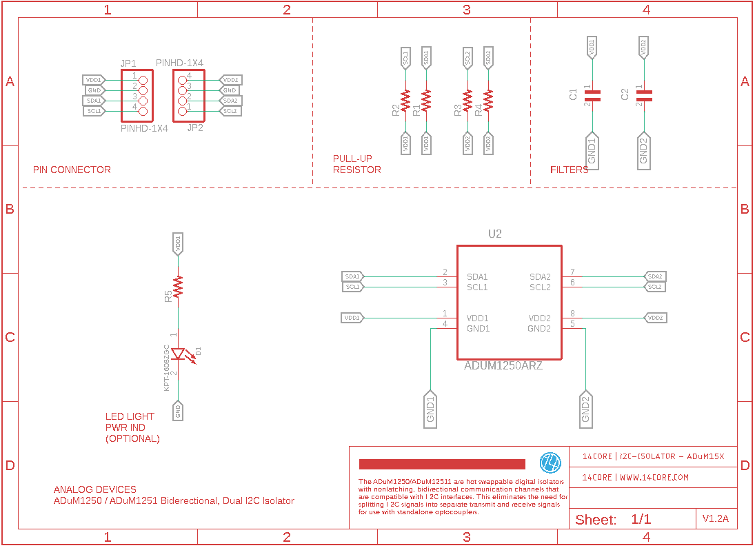
Wiring Diagram / Schematics Example 1
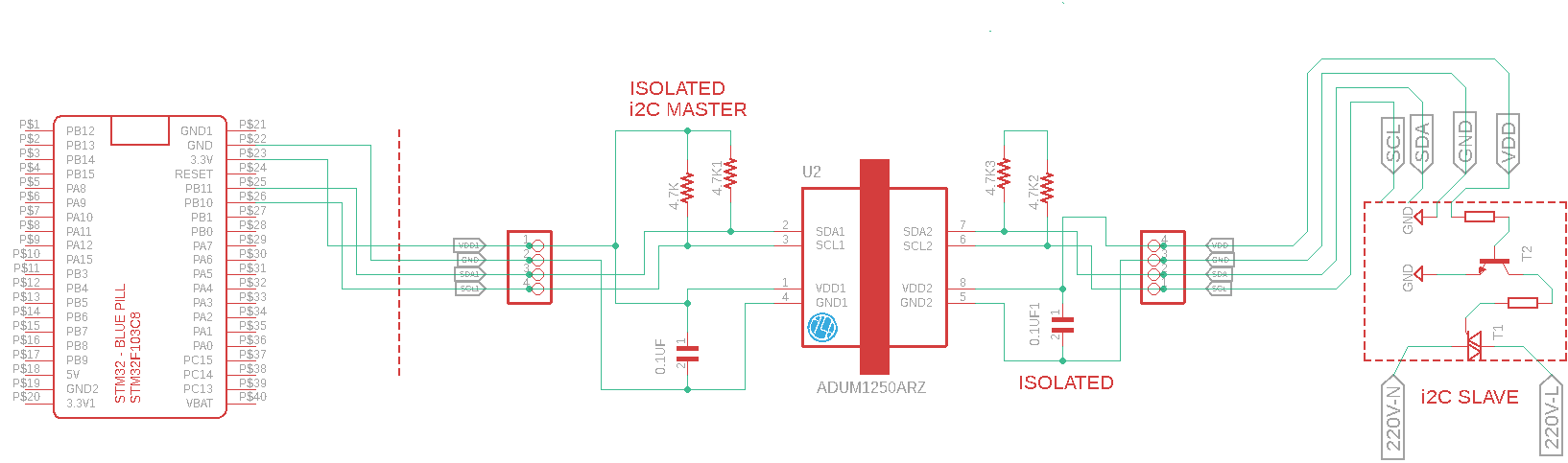
As you can see the diagram were using a pull-up resistors is used to ensure correct operation of the input side of the device. The pull-up resistor helps to define a logical high level for the input signal and ensures a defined voltage level for the input when it is in a high impedance state. Without the pull-up resistor, the input may float to an undefined state, leading to incorrect operation of the device.
The value of the pull-up resistor should be chosen based on the input voltage levels and the input current requirements of the device. The pull-up resistor should be selected such that the input voltage is within the specified voltage range of the device, and the current drawn by the resistor is within the specified input current limits of the device. The value of the pull-up resistor is also dependent on the switching frequency of the input signal, as well as the input capacitance of the device.
In general, the pull-up resistor helps to ensure proper input signal level and signal integrity, which is critical for the correct operation of the ADuM1250. In addition the purpose of the decoupling capacitor is used to provide a stable voltage source for the device and reduce voltage fluctuations caused by changes in the input current. The decoupling capacitor is connected between the VCC pins of the device and provides a low-impedance path for high-frequency noise, which helps to reduce any voltage fluctuations that may occur on the VCC. The value of the decoupling capacitor should be chosen based on the power supply voltage, the maximum input current required by the device, and the switching frequency of the input signals. It is important to choose a decoupling capacitor with a low equivalent series resistance (ESR) to ensure stable operation of the device. In general, the decoupling capacitor helps to ensure stable operation of the ADuM1250 by reducing voltage fluctuations and preserving the power supply voltage, which is critical for the correct operation of the device. For more technical details of the ADuM1250/ADuM1251 Please refer to the datasheet below.
Wiring Diagram / Schematics Example 2
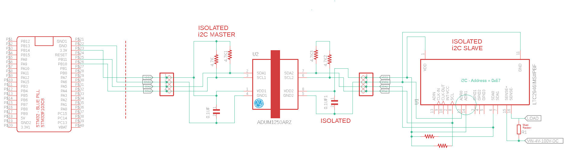
In this example we are going to hook up the LTC2946, LTC2946 is a power and energy monitoring IC designed for use in a variety of applications. It integrates several power measurement functions, including current sensing, voltage sensing, and power calculation, into a single device. The LTC2946 communicates with a microcontroller or host system over the I2C interface, making it a simple and convenient solution for monitoring power and energy consumption in battery-powered systems, renewable energy systems, and other applications where precise power measurements are required. The device can measure voltage, current, and power consumption over a wide range and provides the data in digital format, which can be read over the I2C bus. The LTC2946 also provides several features to enhance system accuracies, such as programmable voltage and current measurement ranges, and multiple independent current sense channels.
LTC2946 Features:
- Wide voltage and current measurement range: The LTC2946 is capable of measuring input voltages up to 80V and can measure current over a wide range from picoamps to tens of amps. The voltage and current measurement ranges are programmable, allowing for maximum measurement accuracy.
- Multiple current sense channels: The LTC2946 provides multiple independent current sense channels, allowing for the monitoring of multiple power sources or loads.
- Energy measurement: The LTC2946 has the ability to measure and accumulate energy consumption over time, making it a useful tool for tracking the energy consumption of a system.
- Power measurement: The LTC2946 calculates power consumption based on the voltage and current measurements, and provides this information in digital format.
- Alerts and Interrupts: The LTC2946 provides programmable alerts and interrupts to signal certain events or conditions, such as overvoltage or overcurrent conditions.
- Power-saving features: The LTC2946 has a low power mode, which allows for reduced power consumption when the device is not actively measuring.
- Ease of use: The LTC2946 is easy to use, as it communicates with the host system over the I2C interface. The I2C interface is a well-established and widely-used communication protocol, making it a convenient choice for a variety of applications.
Overall, the LTC2946 is a versatile and accurate device for monitoring power and energy consumption in a variety of systems. Its combination of features, including multiple current sense channels, energy measurement, and programmable alerts and interrupts, make it a useful tool for monitoring and managing power consumption.
LTC2946 communicates with a microcontroller or host system over the I2C (Inter-Integrated Circuit) bus. I2C is a communication protocol that allows multiple devices to communicate with a single master device (the microcontroller) using just two wires: a data line (SDA) and a clock line (SCL).
The LTC2946 functions as a slave device on the I2C bus, and the microcontroller acts as the master. The LTC2946 sends and receives data to and from the microcontroller over the SDA and SCL lines, using a specific set of commands and data formats (See the download section below).
To communicate with the LTC2946, the microcontroller first sends an I2C start condition and a device address to the LTC2946. The device address identifies the LTC2946 on the I2C bus, and it is followed by a command to specify what action the LTC2946 should take. For example, the microcontroller may send a command to read the current voltage measurement from the LTC2946.
The LTC2946 then sends the requested data back to the microcontroller over the I2C bus, and the microcontroller can read the data and process it as needed. The communication is completed with an I2C stop condition, signaling the end of the transaction.
This process can be repeated multiple times as needed to read different measurement values from the LTC2946 or to configure the device’s settings.
Source Code
[crayon-67ea2b8f46a6e582102318/]
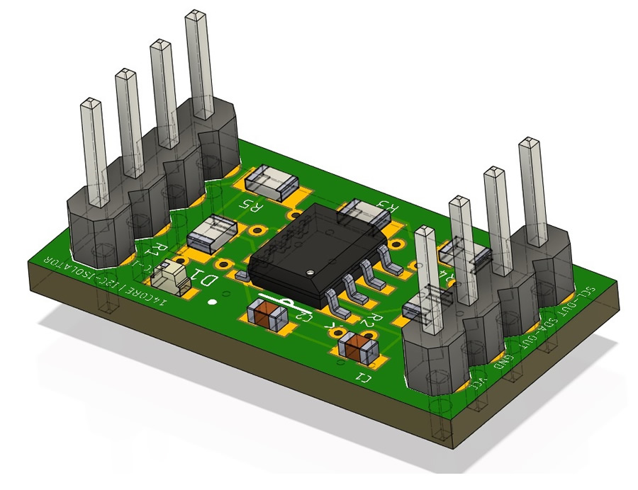
ADuM1250 PCB / Gerber
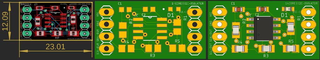

- Download PCB Milling File | 14CORE-ADuM1250
- 14CORE-ADuM1250 Schematics Diagram
- Download Gerber Viewer | Windows | Linux

