Wiring the ADS1115 Analog to Digital Converter with Thermistor on Microcontroller
The ADS1115 is a device that converts Analog to Digital (ADC) driven by i2C Protocol, ADS1115 is a precision analog to digital converter with 16bits of resolution in an ultra-small leadless (QFN) and on a MSPO-10 package. The ADS1115 are designed with precision, power and easy to implement. These device as a feature an on-board reference and oscillator. Data will be communicating via i2C serial interface and can be connected 4 slaves on i2c addresses selection. These device runs on 2.0v to 5.5v.
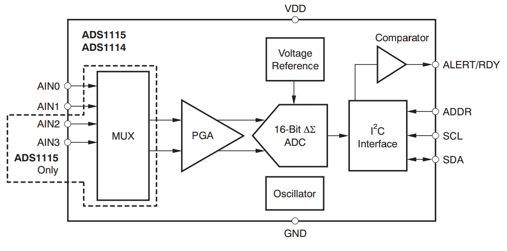
Block Diagram
ADS1115 can perform conversions at rates up to 860 SPS (samples per second) and an on-board PGA is integrated on ADS1115 that offers input range for the supply as low as -+256mV allowing both large and small signals to be measured on a high resolution. Other feature of ADS1115 it has MUX (Multiplexer) that provides two differential or four single ended inputs and operate either on continuous conversation mode or a single-shot mode that automatically powers down after a conversation and reduces current consumption during idle period. The ADS1115 can be used for Portable Instrumentation, Consumer Goods, Battery Monitoring, Temperature Measurement, and Factory Automation and Process Controls.
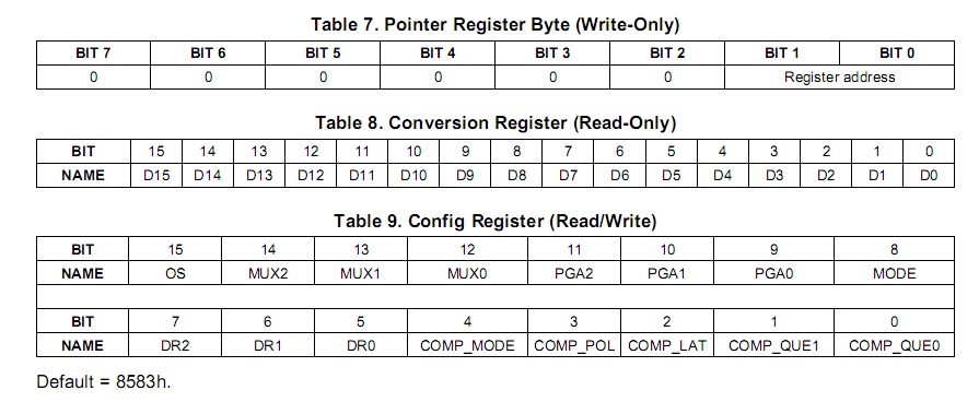
Internal ASD1115 Registers
As you can see the registers of the ADS1115 below. The first block is an 8bit pointer register that directs the data either the 16bit read only conversion register (0) or the 16bit read/write configuration register (1). While the program goes into all the configuration register bits ill cover the most important parts of the configuration register. please refer to the ADS1115 Datasheet
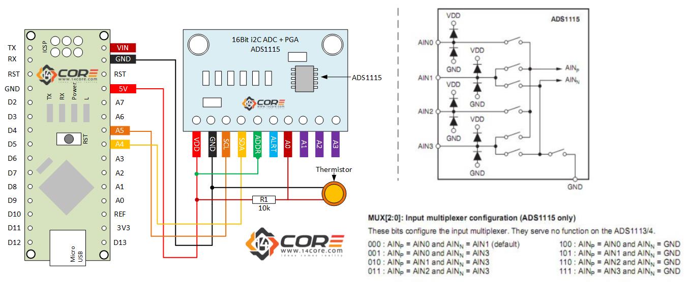
ADS1115 Chip has a base of 7-Bit i2C Address of 0x48 (1001000) and i2c addressing that allow four different addresses using one address (ADR). To program the address connect the pin address as diagram below, up to four boards can be wired.
Source Code / ADS1115 Single Ended on Thermistor
1
2
3
4
5
6
7
8
9
10
11
12
13
14
15
16
17
18
19
20
21
22
23
24
25
26
27
28
29
30
31
32
/********************************************/
/*
14CORE | TEST CODE FOR ADS1115 ANALOG to DIGITAL CONVERSION
www.14core.com / contact@14core.com
*/
*********************************************/
#include <Wire.h>
#include <Adafruit_ADS1015.h>
//Please refer to the diagram above for i2C Address Selection
Adafruit_ADS1115 ads(0x49);
intdoDelay=1000;
intgetVal;
voidsetup(void)
{
Serial.begin(9600);
Serial.println("14CORE | Thermistor Test with ADS1115");
Serial.println("Reading single-ended data from A-IN-0");
We use cookie to provide you the best possible experience, this site uses cookies and by continuing to use the site you agree that we can save them on your device. Cookies are small text files which are placed on your computer and which remember your preference / some details of your visit. Our cookies don’t collect any personal information. For information, please read our Privacy Statement and Cookie Policy , which also explains how to disable this option in your browser. Cookie SettingsACCEPT
Privacy & Cookies Policy
Privacy Overview
This website uses cookies to improve your experience while you navigate through the website. Out of these cookies, the cookies that are categorized as necessary are stored on your browser as they are as essential for the working of basic functionalit...
Necessary cookies are absolutely essential for the website to function properly. This category only includes cookies that ensures basic functionalities and security features of the website. These cookies do not store any personal information.
Any cookies that may not be particularly necessary for the website to function and is used specifically to collect user personal data via analytics, ads, other embedded contents are termed as non-necessary cookies. It is mandatory to procure user consent prior to running these cookies on your website.