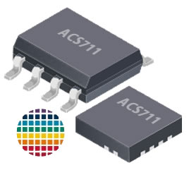
This is the Allegros ±25A, ±31A, ±12A, ±15A ACS711 Hall effect-based linear current sensor an integrated overcurrent fault output, which provides you a low-resistance ~ 1.2mΩ current route including electrical isolation reach to 100 volts. This model receives a bidirectional current input up to 25A and the output of a proportional analog voltage at VCC/2 with a typical error of ±5 percent. The ACS711 operates at 3V ~ 5.5V suitable for 3.3v and 5V system purposes. This Allegro’s ACS711 Hall effect-based linear current sensor Series has integrated fault output; therefore be advised that you need to read carefully the ACS711 datasheets.
There are many uses for the current sensors, for example, some devices are used for power metering, control system diagnostics, current measurement, control some complex loads from electric motors, use for battery charge integration, battery charge monitoring, battery charge condition, commercial appliances, automotive, voltage safety cut-out devices, surge trip protection, high voltage current readings, and many more.
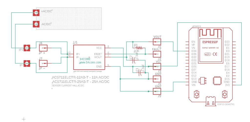
The key features of ACS711 are designed for bidirectional input current from -25A ~ 25A / -12A ~ 12A / -15A ~ 15A / -31A ~ 31A these sensors can survive up to 5 times the overcurrent conditions with the use of a Hall-effect sensor which means that the CHIP can electrically isolate the current path from the sensor for 100V usage which allows the sensor to placed anywhere along the current path and to be used in applications that need electrical isolation. in addition, the ACS711 series has a 100kHz bandwidth with excellent accuracy and reliability the output voltage is extremely stable, particularly since the sensor has zero magnetic hystereses and the overcurrent FAULT output latches LOW when current exceeds negative/positive 25A and operates at a temperature range of -40°C to 125°C. in addition, the schematics below include 4 ACS711 series with 2 LC & EX packages, The first schematic use ACS711ELCTR – 12A / ACS711ELCTR – 25A and the next one is ACS711EEXLT – 15A / ACS11EXLT – 31A depends on your suitable applications. for more technical readings please follow the datasheet below.
Requirements
- Arduino IDE | PlatformIO
- Test Boards :
- Note: The Diagram below is using ESP32 (please refer to your MCU’s respective pin-outs & bus configuration)
- Resistors (See below diagram for required value & alternatives package)
- Capacitor(See below diagram for required value & alternatives package)
1. Wiring Diagram / Schematics for ACS711ELCTR – 12A / ACS711ELCTR – 25A
2. Wiring Diagram / Schematics for ACS711EEXLT – 15A / ACS11EXLT – 31A
Source Code
[crayon-680fcfd86c3d6415857212/]
PCB Milling / Gerber File
- Download PCB Milling File | LC Package | EX Package
- Download Gerber Viewer | Windows | Linux


