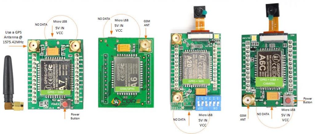
This is A7, A6C, and A6 is a GSM/GPRS/GPS Module that Supports GSM, GPRS, and GPS Quad-Band 850/900/1800/1900 MHz 2G GSM network worldwide with an SMS, GPRS Class 10 Data Service, and GPS feature and supports digital audio and analog audio support for HR, FR, EFR, AMR speech coding, there is another module that comes from this series the A2 & A20.
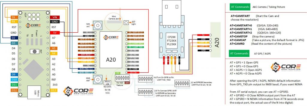
A2/A20 is GSM/GPRS/GPS + WIFI with ESP8266/8285 Wi-Fi IC onboard, GSM / GPRS four frequency bands including 850, 900, 1800, 1900MHz and it has four working mode the GPRS mode, Wi-Fi mode, both mode, Wi-Fi control GPRS and camera mode. Use ESP8266/8285 secondary UART port that required a code to drive the ESP8266/ESP8285. The A2/A20 you can simply develop a wireless GPS tracking device or a monitoring device can be used in industrial, agricultural monitoring, outdoor monitoring, intelligent home appliance, driving test, fingerprint/face machine, and video doorbell, etc. another function of A6C and A20 is can capture a photo via GPRS or Wi-Fi switch transmission. The A7, A6C, A6, A20 module is controlled by using AT command via UART supplied by 3.3v / 4.2v logic level.
Required Components
- Arduino Microcontrollers, Teensy, ESP8266, ATMEGA328 16/12, ATMEGA32u4 16/8/ MHz, ESP8266, ATMEGA250 16 MHz, ATSAM3x8E, ATSAM21D, ATTINY8516/8 MHz (Note: The Diagram below is using NANO. If you’re using other MCU please refer to the respective pin-outs.
- USB TTL/UART
- A2 / A7 / A6C / A6 Module
- Jumper Wire / DuPont Wire
- Solder Less Bread Board
Wiring Diagram for A7 / A6C / A6
Wiring Diagram for A2 / A20
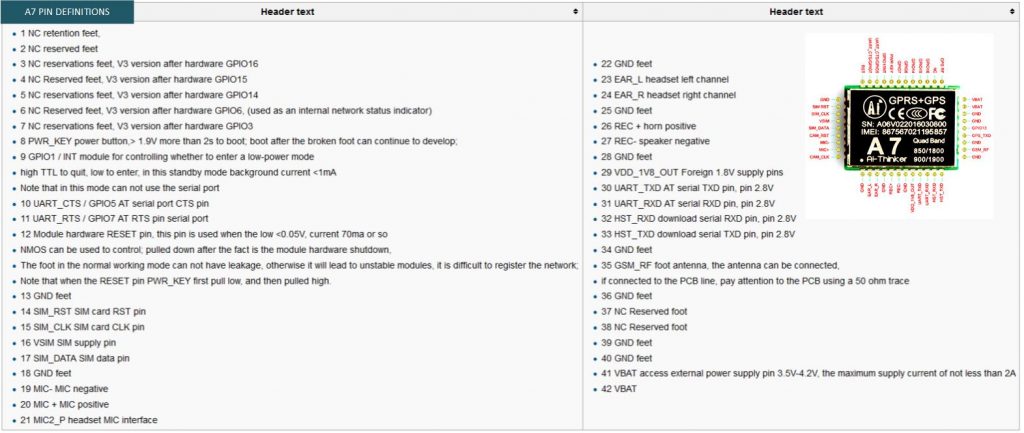
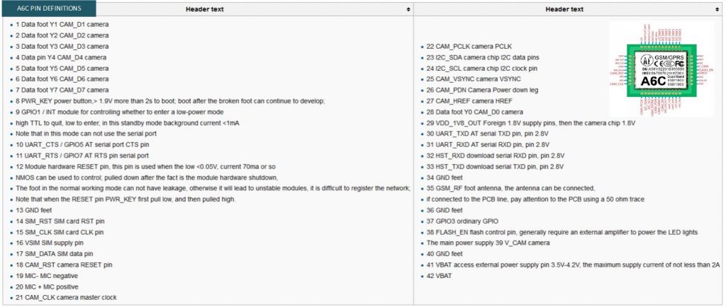
Pin-outs Definitions
AT Command Tester
Working on AT – Command please see AT-Command documentation manual or you can use the AT-Command tester which can be downloaded below.
Test Sketch Code
[crayon-67ea89c2e3a6a487221057/]
Downloads
- GSM AT Command Error Code List | FILE
- Download AT-Command Datasheet Manual for A7 – A6 – A6C | PDF 1 | PDF 2
- Download AT-Command Datasheet Manual for A20 | PDF
- Download A7 Breakout Schematics Diagram | LINK
- Download A6C Breakout Schematics Diagram| LINK
- Download A6 Breakout Schematics Diagram | LINK
- Download A20 Breakout Schematics Diagram | PDF
- Download Serial Tools | RealTerm | Putty | CoolTerm | TeraTerm
- Download AT Command Test Tool > http://m2msupport.net/m2msupport/download-at-command-tester/


