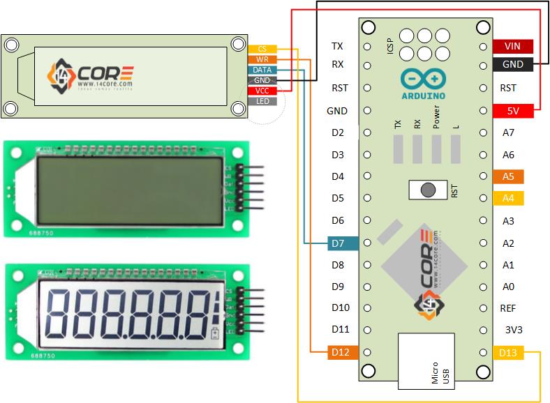
This is another illustration how to wire the HT621 driven 6 Digit 7 Segment LCD Display on Microcontroller. This module is widely used in multi-meter, voltage monitor, solar power monitor, clock, thermometer, electronic measuring device, automotive, etc. this module is compatible in your favorite Microcontroller using 3 wire SPI communication and it has a backlight suitable in dark environment. This module runs on 4.7~5.2V DC 0.4mA without back-light and 4mA with back-light.
Required Components
- Arduino Microcontroller, ESP8266 12, 12E, ESP8266 NodeMCU, ESPDuino, WeMos, ATMEGA328 16/12, ATMEGA32u4 16/8/ MHz, ESP8266, ATMEGA250 16 MHz, ATSAM3x8E, ATSAM21D, ATTINY85 16/8 MHz (Note: The Diagram below is using NANO. If your using other MCU please refer to the respective pin-outs
- 6 Digit 7 Segment 2.4 Inch LCD Display Module
- Jumper Wires / DuPont Wire
Wiring Guide
Source Code
|
1 2 3 4 5 6 7 8 9 10 11 12 13 14 15 16 17 18 19 20 21 22 23 24 25 26 27 28 29 30 31 32 33 34 35 36 37 38 39 40 41 42 43 44 45 46 47 48 49 50 51 52 53 54 55 56 57 58 59 60 61 62 63 64 65 66 67 68 69 70 71 72 73 74 75 76 77 78 79 80 81 82 83 84 85 86 87 88 89 90 91 92 93 94 95 96 97 98 99 100 101 102 103 104 105 106 107 108 109 110 111 112 113 114 115 116 117 118 119 120 121 122 123 124 125 126 127 128 129 130 131 132 133 134 135 136 137 138 139 140 141 142 143 144 145 146 147 148 149 150 151 152 153 154 155 156 157 158 159 160 161 162 163 164 165 166 |
#define CS 13 //Pin 13 as chip selection output #define WR 12 //Pin 12 as read clock output #define DATA 7 //Pin 7 as Serial data output #define CS1 digitalWrite(CS, HIGH) #define CS0 digitalWrite(CS, LOW) #define WR1 digitalWrite(WR, HIGH) #define WR0 digitalWrite(WR, LOW) #define DATA1 digitalWrite(DATA, HIGH) #define DATA0 digitalWrite(DATA, LOW) #define sbi(x, y) (x |= (1 << y)) #define cbi(x, y) (x &= ~(1 <<y )) #define uchar unsigned char #define uint unsigned int //定义HT1621的命令 #define ComMode 0x52 //4COM,1/3bias 1000 010 1001 0 #define RCosc 0x30 //1000 0011 0000 #define LCD_on 0x06 /1000 0000 0 11 0 #define LCD_off 0x04 #define Sys_en 0x02 //1000 0000 0010 #define CTRl_cmd 0x80 #define Data_cmd 0xa0 /*0,1,2,3,4,5,6,7,8,9,A,b,C,c,d,E,F,H,h,L,n,N,o,P,r,t,U,-, ,*/ const char num[]={0x7D,0x60,0x3E,0x7A,0x63,0x5B,0x5F,0x70,0x7F,0x7B,0x77,0x4F,0x1D,0x0E,0x6E,0x1F,0x17,0x67,0x47,0x0D,0x46,0x75,0x37,0x06,0x0F,0x6D,0x02,0x00,}; //0 1 2 3 4 5 6 7 8 9 char dispnum[6]={0x00,0x00,0x00,0x00,0x00,0x00}; void SendBit_1621(uchar sdata,uchar cnt) { //data cnt HT1621 uchar i; for(i=0;i<cnt;i++) { WR0; if(sdata&0x80) DATA1; else DATA0; WR1; sdata<<=1; } } void SendCmd_1621(uchar command) { CS0; SendBit_1621(0x80,4); SendBit_1621(command,8); CS1; } void Write_1621(uchar addr,uchar sdata) { addr<<=2; CS0; SendBit_1621(0xa0,3); SendBit_1621(addr,6); SendBit_1621(sdata,8); CS1; } void HT1621_all_off(uchar num) { uchar i; uchar addr=0; for(i=0;i<num;i++) { Write_1621(addr,0x00); addr+=2; } } void HT1621_all_on(uchar num) { uchar i; uchar addr=0; for(i=0;i<num;i++) { Write_1621(addr,0xff); addr+=2; } } void Init_1621(void) { SendCmd_1621(Sys_en); SendCmd_1621(RCosc); SendCmd_1621(ComMode); SendCmd_1621(LCD_on); } void displaydata(int p) { uchar i=0; switch(p) { case 1: sbi(dispnum[0],7); break; case 2: sbi(dispnum[1],7); break; case 3: sbi(dispnum[2],7); break; default:break; } for(i=0;i<=5;i++) { Write_1621(i*2,dispnum[i]); } } void setup() { pinMode(CS, OUTPUT); // pinMode(WR, OUTPUT); // pinMode(DATA, OUTPUT); // CS1; DATA1; WR1; delay(50); Init_1621(); HT1621_all_on(16); //1621 delay(1000); HT1621_all_off(16); //1621 delay(1000); displaydata(1);//light on the first decimal point starting from the right side dispnum[5]=num[5]; dispnum[4]=num[4]; dispnum[3]=num[3]; dispnum[2]=num[2]; dispnum[1]=num[1]; dispnum[0]=num[0]; sbi(dispnum[5],7); //cbi(dispnum[5],7); sbi(dispnum[4],7); //cbi(dispnum[4],7); sbi(dispnum[3],7); //cbi(dispnum[3],7); //Write_1621(0,num[0]); //Write_1621(2,num[28]); //Write_1621(4,num[2]); //Write_1621(6,num[28]); //Write_1621(8,num[4]); //Write_1621(10,num[5]); } void loop() { // you can place your main code here to run repeatedly } |
Wiring the 6 Digit 7 Segment 2.4 Inch HT1621 LCD Display Module on Microcontroller


Greetings!
I have a Display of this but it is with 5 digits and I would like to do something, like a clock but I do not have enough knowledge; I would like some code and / or some help; Thank you
Hi Daniel,
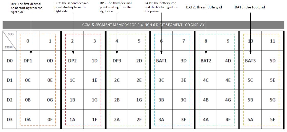
Just look for the matrix address on each segment. for example if it is 5 digital you just going to change char to display to 5 digit. see below example. look also the datasheet of your LCD for your reference because each device has its own address and mapping, depends on the manufacturer.
Change this to 5 digit >>c har dispnum[5]={0x00,0x00,0x00,0x00,0x00};
OK friend! I’ll try; I would like a clock code with arduino but thanks for the reply!
Greetings friend!
I did as you told me, but all I can see on the Display is only a Segment (risk) in one of the Digits; Could you give me more tips?
I would like to use this Display to show the Time but I do not have enough knowledge!
Thank you very much
Yes Enrico! That way it worked with this code but, and to make a simple clock with the flashing dots like I would? Thank you
Hello how can we turn down the LED brightness? It is way to bright.
hI!, just attach a resistor to LED pin or you can also hookup a Potensiometer attach to LED Pin. ;)
Which value for the resistor ?
There is no resistor in the diagram above, however you can use 1k…
Can you Give me your gmail ?
I request you that I have to drive 3 lcd with HT1621IC.
Here is the link.
https://www.instructables.com/How-to-Wire-the-6-Digit-7-Segment-24-Inch-Ht1621-L/
How to write code for 4 digit lcd?
Hello,
I am using the HT1621B with a plain glass LCD, 3.5 Digit. This display had only 1 COM , whereas the HT1621 had provision for 4 COMs. Can you suggest what Init parameters would be suitable ?
#define RCosc 0x30 //1000 0011 0000
I dont know if this is an error, but as per datasheet for internal OSC it should be 0x18
Cheers !!