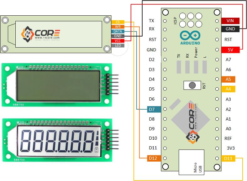
#define CS 13 //Pin 13 as chip selection output
#define WR 12 //Pin 12 as read clock output
#define DATA 7 //Pin 7 as Serial data output
#define CS1 digitalWrite(CS, HIGH)
#define CS0 digitalWrite(CS, LOW)
#define WR1 digitalWrite(WR, HIGH)
#define WR0 digitalWrite(WR, LOW)
#define DATA1 digitalWrite(DATA, HIGH)
#define DATA0 digitalWrite(DATA, LOW)
#define sbi(x, y) (x |= (1 << y))
#define cbi(x, y) (x &= ~(1 <<y ))
#define uchar unsigned char
#define uint unsigned int
//定义HT1621的命令
#define ComMode 0x52 //4COM,1/3bias 1000 010 1001 0
#define RCosc 0x30 //1000 0011 0000
#define LCD_on 0x06 /1000 0000 0 11 0
#define LCD_off 0x04
#define Sys_en 0x02 //1000 0000 0010
#define CTRl_cmd 0x80
#define Data_cmd 0xa0
/*0,1,2,3,4,5,6,7,8,9,A,b,C,c,d,E,F,H,h,L,n,N,o,P,r,t,U,-, ,*/
const char num[]={0x7D,0x60,0x3E,0x7A,0x63,0x5B,0x5F,0x70,0x7F,0x7B,0x77,0x4F,0x1D,0x0E,0x6E,0x1F,0x17,0x67,0x47,0x0D,0x46,0x75,0x37,0x06,0x0F,0x6D,0x02,0x00,};
//0 1 2 3 4 5 6 7 8 9
char dispnum[6]={0x00,0x00,0x00,0x00,0x00,0x00};
void SendBit_1621(uchar sdata,uchar cnt)
{
//data cnt HT1621
uchar i;
for(i=0;i<cnt;i++)
{
WR0;
if(sdata&0x80) DATA1;
else DATA0;
WR1;
sdata<<=1;
}
}
void SendCmd_1621(uchar command)
{
CS0;
SendBit_1621(0x80,4);
SendBit_1621(command,8);
CS1;
}
void Write_1621(uchar addr,uchar sdata)
{
addr<<=2;
CS0;
SendBit_1621(0xa0,3);
SendBit_1621(addr,6);
SendBit_1621(sdata,8);
CS1;
}
void HT1621_all_off(uchar num)
{
uchar i;
uchar addr=0;
for(i=0;i<num;i++)
{
Write_1621(addr,0x00);
addr+=2;
}
}
void HT1621_all_on(uchar num)
{
uchar i;
uchar addr=0;
for(i=0;i<num;i++)
{
Write_1621(addr,0xff);
addr+=2;
}
}
void Init_1621(void)
{
SendCmd_1621(Sys_en);
SendCmd_1621(RCosc);
SendCmd_1621(ComMode);
SendCmd_1621(LCD_on);
}
void displaydata(int p)
{
uchar i=0;
switch(p)
{
case 1:
sbi(dispnum[0],7);
break;
case 2:
sbi(dispnum[1],7);
break;
case 3:
sbi(dispnum[2],7);
break;
default:break;
}
for(i=0;i<=5;i++)
{
Write_1621(i*2,dispnum[i]);
}
}
void setup() {
pinMode(CS, OUTPUT); //
pinMode(WR, OUTPUT); //
pinMode(DATA, OUTPUT); //
CS1;
DATA1;
WR1;
delay(50);
Init_1621();
HT1621_all_on(16); //1621
delay(1000);
HT1621_all_off(16); //1621
delay(1000);
displaydata(1);//light on the first decimal point starting from the right side
dispnum[5]=num[5];
dispnum[4]=num[4];
dispnum[3]=num[3];
dispnum[2]=num[2];
dispnum[1]=num[1];
dispnum[0]=num[0];
sbi(dispnum[5],7);
//cbi(dispnum[5],7);
sbi(dispnum[4],7);
//cbi(dispnum[4],7);
sbi(dispnum[3],7);
//cbi(dispnum[3],7);
//Write_1621(0,num[0]);
//Write_1621(2,num[28]);
//Write_1621(4,num[2]);
//Write_1621(6,num[28]);
//Write_1621(8,num[4]);
//Write_1621(10,num[5]);
}
void loop() {
// you can place your main code here to run repeatedly
}


Greetings!
I have a Display of this but it is with 5 digits and I would like to do something, like a clock but I do not have enough knowledge; I would like some code and / or some help; Thank you
Hi Daniel,
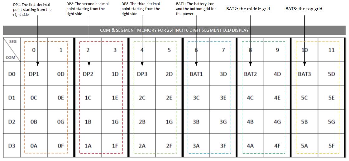
Just look for the matrix address on each segment. for example if it is 5 digital you just going to change char to display to 5 digit. see below example. look also the datasheet of your LCD for your reference because each device has its own address and mapping, depends on the manufacturer.
Change this to 5 digit >>c har dispnum[5]={0x00,0x00,0x00,0x00,0x00};
OK friend! I’ll try; I would like a clock code with arduino but thanks for the reply!
Greetings friend!
I did as you told me, but all I can see on the Display is only a Segment (risk) in one of the Digits; Could you give me more tips?
I would like to use this Display to show the Time but I do not have enough knowledge!
Thank you very much
Yes Enrico! That way it worked with this code but, and to make a simple clock with the flashing dots like I would? Thank you
Hello how can we turn down the LED brightness? It is way to bright.
hI!, just attach a resistor to LED pin or you can also hookup a Potensiometer attach to LED Pin. ;)
Which value for the resistor ?
There is no resistor in the diagram above, however you can use 1k…
Can you Give me your gmail ?
I request you that I have to drive 3 lcd with HT1621IC.
Here is the link.
https://www.instructables.com/How-to-Wire-the-6-Digit-7-Segment-24-Inch-Ht1621-L/
How to write code for 4 digit lcd?
Hello,
I am using the HT1621B with a plain glass LCD, 3.5 Digit. This display had only 1 COM , whereas the HT1621 had provision for 4 COMs. Can you suggest what Init parameters would be suitable ?
#define RCosc 0x30 //1000 0011 0000
I dont know if this is an error, but as per datasheet for internal OSC it should be 0x18
Cheers !!