


This is another sensor that works and runs on the i2C protocol produced and developed by Analog Devices Semiconductor, Analog Devices are known for their reliable and well-documented sensor chip and their primary electronics components. The Analog Devices ADT7410 is one of their top-notch temperature sensor featuring a high precision and high-resolution sensor with a 16-bit at 0.0078°C temperature resolution and 0.5°C temperature tolerance including an interrupt and critical-temperature alert pins with a supply voltage from 2.7v ~ 5.5v Logic, for each integration on your projects.


The ADT7410 has 2 address pins which means that you can have up to 4 sensors in one i2C communication BUS. For more technical details and configuration settings please refer to the technical datasheet below.
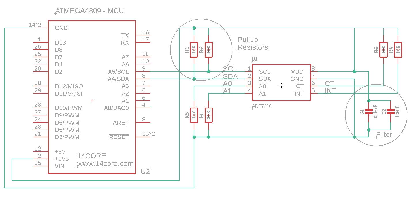
The ADT7410 Pin Configuration, Function and Descriptions
ADT7410 i2C Address – 0x49
- PIN 1 | SCL | I2C Serial Clock Input. The serial clock is used to clock in and clock out data to and from any register of the ADT7410. Open-drain configuration. A pull-up resistor is required, typically 10 kΩ.
- PIN 2 | SDA | I2C Serial Data Input/Output. Serial data to and from the part is provided on this pin. Open-drain configuration. A pull-up resistor is required, typically 10 kΩ.
- PIN 3 | A0 | I2C Serial Bus Address Selection Pin. Logic input. Connect to GND or VDD to set an I2C address.
- PIN 4 | A1 | I2C Serial Bus Address Selection Pin. Logic input. Connect to GND or VDD to set an I2C address.
- PIN 5 | INT | Over-temperature and Under-temperature Indicator. Logic output. Power-up default setting is as an active low comparator interrupt. Open-drain configuration. A pull-up resistor is required, typically 10 kΩ.
- PIN 6 | CT | Critical Over-temperature Indicator. Logic output. Power-up default polarity is active low. Open-drain configuration. A pull-up resistor is required, typically 10 kΩ.
- PIN 7 | GND | Analog and Digital Ground.
- PIN 8 | VDD | Positive Supply Voltage (2.7 V to 5.5 V). Decouple the supply with a 0.1 μF ceramic capacitor to ground.
Requirements
- Arduino IDE | PlatformIO
- Test Boards :
- Note: The Diagram below is using ATMEGA4809 / Arduino Nano Every Microcontroller (please refer to your MCU’s respective pin-outs & bus configuration)
- Resistors (See below diagram for required value)
- Capacitor(See below diagram for required value)
Wiring Diagram & Schematics
Source Code & Test Code
[crayon-67f8cea8bafc5554637681/]
CircuitPhython MCU Connections
First thing first you need to wire your AD7410 to your ESP32/RPI/PICO devices that support CircuitPython Firmware and hookup to: BOARD 3V –> ADT7410 – VCC / VIN | BOARD GND –> ADT7410 GND | BOARD SCL –> ADT7410 – SCL | BOARD SDA –> ADT7410 SDA
[crayon-67f8cea8bafce922880676/]
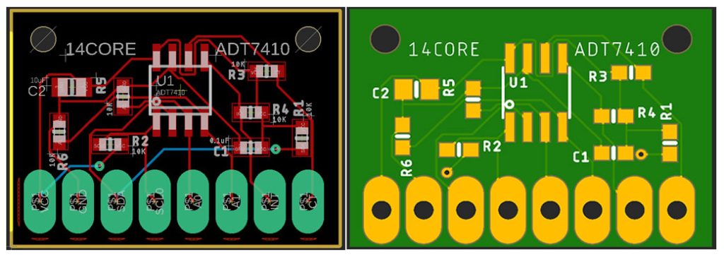
PCB Board Milling / Gerber File

Downloads
- Download ADT17410 Datasheet | PDF
- Download ADT1710 Code Library | ZIP
- Download Adafruit CircuitPython Library | ZIP

