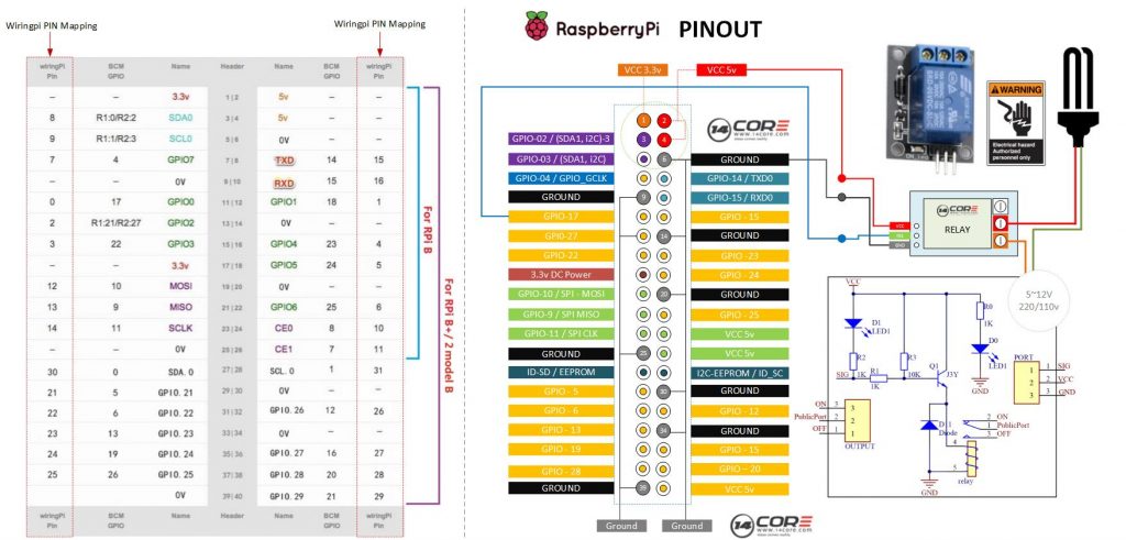
Another illustration how to wire the single channel relay with Raspberry Pi. Relays are suitable for driving high Power AC/DC electrical equipment such as home appliances, light bulbs, motors, etc. Mostly popular in industrial and automotive use for automation. By using a relay you can drive any high power device with low power voltage input by connecting to Microcontroller or Raspberry Pi. Relay is a kind of switching device that has a rounded coil inside or rounded iron core that driven by electromagnet when charge apply to the coil it will turn to normally close. As you can see the diagram below it use GPIO-0 when the GPIO 0 output turn HIGH state the Relay will change the coil then change to NC.
Component Required
- Raspberry Pi / Banana Pi / Orange Pi (If your using Banana Pi or Orange Pi See first the GPIO Pins)
- Single Channel Relay Module
- Solder Less Breadboard
- Jumper Wire / DuPont Wire
Wiring Diagram
C Source Code
1 2 3 4 5 6 7 8 9 10 11 12 13 14 15 16 17 18 19 20 21 22 23 24 25 26 27 28 29 30 31 32 33 34 35 36 37 38 39 40 41 |
/* 14CORE Test Code for: Single Channel Relay .:+osysso++:` `+yhs/-` `-+s+` `:/+++++++++` .:/++ooo++/-` .ooooooooooo+: :///////////- `odh/` `:y+` /ddhsooooooo+ /hddhsooooydddh sdddoooooosdddy` `////////////` -hds` `sy. +ddy` .ddd: sddy.dddo +ddd- .-----------` `hds :sssss/ -ossssso-yy` `hdd: oddy `ddd/oddd:......+dddo .++++++++++++ +dd` :sdddh` :ydddddddo +y/ .ddd+........ `hddy:.....:yddy.hdddddddddddy+. ```````````` ydy .hddd/+hdddhydddh/.+yo /hdddddddddd. :shddddddddhs/`+ddd:````-yddy- :ooooooooooo+ odh` sdddooyyyyyhddddyy.sy+ ` `......... ``.... ....` ```...` ` `` `` ` -dd+`::::` .:::- /yy. -oos+:-oos+--oos+: /o `+y o/: o:+/ h:`yos /+-`/+/+ s:y/y. /dd/ `+yy: +//+ +/:+ +/:+ -. `/ -:o.:/:`//+- + +:- :`-+:`://: +`o`+. -yds. `/yys- .`-.. .``` ```` .`` ` ` ``` ``-..` ` :ydy/.`````.-/oyhs: `+++oo+oo+:.+-++/-/ooo+o +:o/oo///:+/ .:oyhhhhhhhso:` `. ``` */ #include <wiringPi.h> #include <stdio.h> #define RelayPn 0 int main(void) { if(wiringPiSetup() == -1){ //If wiringpi initialization failed, printf printf("Wiring Pi Initialization Faild"); return 1; } pinMode(RelayPn, OUTPUT); while(1){ digitalWrite(RelayPn, LOW); delay(1000); digitalWrite(RelayPn, HIGH); delay(1000); } return 0; } |
Python Source Code
1 2 3 4 5 6 7 8 9 10 11 12 13 14 15 16 17 18 19 20 21 22 23 24 25 26 27 28 29 30 31 32 33 34 35 36 37 38 39 40 41 42 43 44 45 46 |
# 14CORE Test Code for: Single Channel Relay Test Code # .:+osysso++:` # `+yhs/-` `-+s+` `:/+++++++++` .:/++ooo++/-` .ooooooooooo+: :///////////- # `odh/` `:y+` /ddhsooooooo+ /hddhsooooydddh sdddoooooosdddy` `////////////` # -hds` `sy. +ddy` .ddd: sddy.dddo +ddd- .-----------` # `hds :sssss/ -ossssso-yy` `hdd: oddy `ddd/oddd:......+dddo .++++++++++++ # +dd` :sdddh` :ydddddddo +y/ .ddd+........ `hddy:.....:yddy.hdddddddddddy+. ```````````` # ydy .hddd/+hdddhydddh/.+yo /hdddddddddd. :shddddddddhs/`+ddd:````-yddy- :ooooooooooo+ # odh` sdddooyyyyyhddddyy.sy+ ` `......... ``.... ....` ```...` ` `` `` ` # -dd+`::::` .:::- /yy. -oos+:-oos+--oos+: /o `+y o/: o:+/ h:`yos /+-`/+/+ s:y/y. # /dd/ `+yy: +//+ +/:+ +/:+ -. `/ -:o.:/:`//+- + +:- :`-+:`://: +`o`+. # -yds. `/yys- .`-.. .``` ```` .`` ` ` ``` ``-..` ` # :ydy/.`````.-/oyhs: `+++oo+oo+:.+-++/-/ooo+o +:o/oo///:+/ # .:oyhhhhhhhso:` `. ``` #!/usr/bin/env python import RPi.GPIO as GPIO import time RelayPin = 11 # Set pin11 as Out def setup(): GPIO.setmode(GPIO.BOARD) # Set GPIO as numbering GPIO.setup(RelayPin, GPIO.OUT) GPIO.output(RelayPin, GPIO.HIGH) def loop(): while True: print 'Relay Channel One is On' GPIO.output(RelayPin, GPIO.LOW) time.sleep(0.5) print 'Relay Channel One is Off' GPIO.output(RelayPin, GPIO.HIGH) time.sleep(0.5) def destroy(): GPIO.output(RelayPin, GPIO.HIGH) GPIO.cleanup() if __name__ == '__main__': # Program start from here setup() try: loop() except KeyboardInterrupt: # When Control C is pressed program will destroy() destroy() |