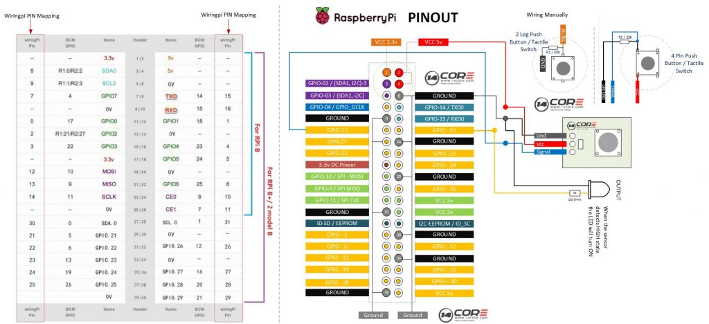
Push buttons are simple switch mechanism for controlling some aspect of a machine or a process. Buttons are typically made out of plastics, metal, carbons or rubber. The surface is usually flat or shaped to accommodate the human finger or hand, to that it easy to depressed or press. Buttons are most often biased switch through even many un-biased button due to physical characteristics. Push buttons required a spring or a rubber to return their state. As you can see the illustration below the push button as assigned as an input to our raspberry pi so when the push button is pressed the GPIO will change to LOW LEVEL or 0v. If the GPIO turns into LOW LEVEL means the button is pressed then we can run the corresponding code. In this experiment, we will show a char or a string on our output while the LED will turn to high state.
Required Components
- Raspberry Pi / Banana Pi / Orange Pi (If your using Banana Pi or Orange Pi See first the GPIO Pins)
- Push Buttons / Push Button Module
- 10k Resistor (Optional)
- Solder-less breadboard
- Jumper Wire / DuPont Wire
Wiring Diagram
C Source Code
1 2 3 4 5 6 7 8 9 10 11 12 13 14 15 16 17 18 19 20 21 22 23 24 25 26 27 28 29 30 31 32 33 34 35 36 37 38 39 40 41 42 43 44 45 46 47 48 49 50 51 52 53 54 55 56 57 58 59 60 61 62 63 64 65 66 67 68 69 |
/* 14CORE Test Code for: Tilt Switch on C Code .:+osysso++:` `+yhs/-` `-+s+` `:/+++++++++` .:/++ooo++/-` .ooooooooooo+: :///////////- `odh/` `:y+` /ddhsooooooo+ /hddhsooooydddh sdddoooooosdddy` `////////////` -hds` `sy. +ddy` .ddd: sddy.dddo +ddd- .-----------` `hds :sssss/ -ossssso-yy` `hdd: oddy `ddd/oddd:......+dddo .++++++++++++ +dd` :sdddh` :ydddddddo +y/ .ddd+........ `hddy:.....:yddy.hdddddddddddy+. ```````````` ydy .hddd/+hdddhydddh/.+yo /hdddddddddd. :shddddddddhs/`+ddd:````-yddy- :ooooooooooo+ odh` sdddooyyyyyhddddyy.sy+ ` `......... ``.... ....` ```...` ` `` `` ` -dd+`::::` .:::- /yy. -oos+:-oos+--oos+: /o `+y o/: o:+/ h:`yos /+-`/+/+ s:y/y. /dd/ `+yy: +//+ +/:+ +/:+ -. `/ -:o.:/:`//+- + +:- :`-+:`://: +`o`+. -yds. `/yys- .`-.. .``` ```` .`` ` ` ``` ``-..` ` :ydy/.`````.-/oyhs: `+++oo+oo+:.+-++/-/ooo+o +:o/oo///:+/ .:oyhhhhhhhso:` `. ``` */ #include <wiringPi.h> #include <stdio.h> #define SensorPin 0 #define LedOutput 1 void INOUT(char* ledstate) { pinMode(Rpin, OUTPUT); if (ledstate == "OUTPUT") { digitalWrite(LedOutput, HIGH); } else if (ledstate == "INPUT") { digitalWrite(LedOutput, LOW); } else printf("Error Led Output"); } int main(void) { if(wiringPiSetup() == -1) //If no response from wiringpi.h print { printf("Wiring Pi Initialization Faild"); return 1; } pinMode(SensorPin, INPUT); INOUT("INPUT"); while(1){ if(0 == digitalRead(SensorPin)){ delay(10); if(0 == digitalRead(SensorPin)){ INOUT("OUTPUT"); printf("Button is pressed\n"); } } else if(1 == digitalRead(SensorPin)){ delay(10); if(1 == digitalRead(SensorPin)){ while(!digitalRead(SensorPin)); INOUT("INPUT"); } } } return 0; } |
Python Source Code
1 2 3 4 5 6 7 8 9 10 11 12 13 14 15 16 17 18 19 20 21 22 23 24 25 26 27 28 29 30 31 32 33 34 35 36 37 38 39 40 41 42 43 44 45 46 47 48 49 50 51 52 53 54 |
# 14CORE Test Code for: Ball Tilt Switch on Raspberry Pi # .:+osysso++:` # `+yhs/-` `-+s+` `:/+++++++++` .:/++ooo++/-` .ooooooooooo+: :///////////- # `odh/` `:y+` /ddhsooooooo+ /hddhsooooydddh sdddoooooosdddy` `////////////` # -hds` `sy. +ddy` .ddd: sddy.dddo +ddd- .-----------` # `hds :sssss/ -ossssso-yy` `hdd: oddy `ddd/oddd:......+dddo .++++++++++++ # +dd` :sdddh` :ydddddddo +y/ .ddd+........ `hddy:.....:yddy.hdddddddddddy+. ```````````` # ydy .hddd/+hdddhydddh/.+yo /hdddddddddd. :shddddddddhs/`+ddd:````-yddy- :ooooooooooo+ # odh` sdddooyyyyyhddddyy.sy+ ` `......... ``.... ....` ```...` ` `` `` ` # -dd+`::::` .:::- /yy. -oos+:-oos+--oos+: /o `+y o/: o:+/ h:`yos /+-`/+/+ s:y/y. # /dd/ `+yy: +//+ +/:+ +/:+ -. `/ -:o.:/:`//+- + +:- :`-+:`://: +`o`+. # -yds. `/yys- .`-.. .``` ```` .`` ` ` ``` ``-..` ` # :ydy/.`````.-/oyhs: `+++oo+oo+:.+-++/-/ooo+o +:o/oo///:+/ # .:oyhhhhhhhso:` `. ``` #!/usr/bin/env python import RPi.GPIO as GPIO TiltSensorPin = 11 #Sensor is connected to GPIO 17 LedOutputPin = 12 #Outlet led is connected to GPIO 15 Led_status = 1 def setup(): GPIO.setmode(GPIO.BOARD) # GPIO will be numbered GPIO.setup(LedOutputPin, GPIO.OUT) # Set LedOutputPin's mode is output GPIO.setup(TiltSensorPin, GPIO.IN, pull_up_down=GPIO.PUD_UP) GPIO.output(LedOutputPin, GPIO.HIGH) # Set LedOutputPin high def swLed(ev=None): global Led_status Led_status = not Led_status GPIO.output(LedOutputPin, Led_status) # switch led status(on-->off; off-->on) if Led_status == 1: print '14CORE | OUTPUT LED TURN OFF' else: print '14CORE | OUTPUT LED TURN ON' def loop(): GPIO.add_event_detect(TiltSensorPin, GPIO.FALLING, callback=swLed) # wait for falling while True: pass # Do nothing def destroy(): GPIO.output(LedOutputPin, GPIO.HIGH) # Led will turn On GPIO.cleanup() # Rlease or clean resource if __name__ == '__main__': setup() try: loop() except KeyboardInterrupt: # When press control C child program will distroy destroy() |