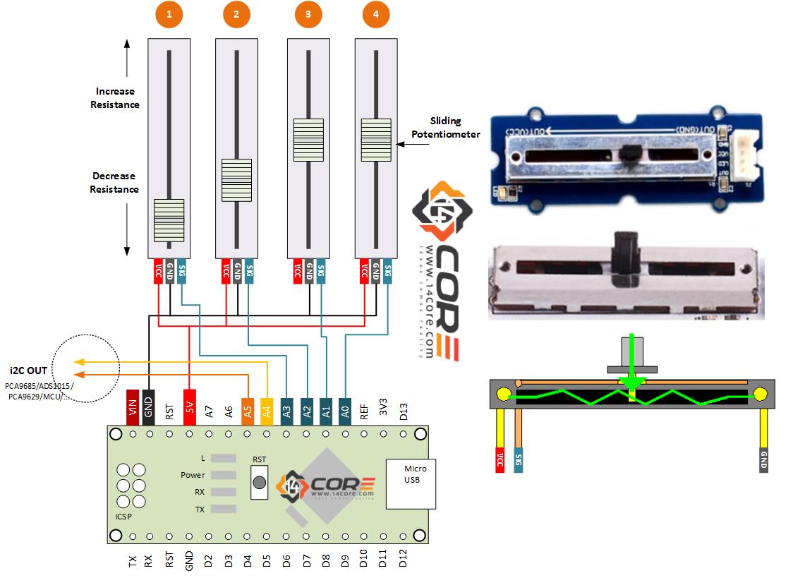
This is the sliding Potentiometer that provides intuitive benefits in to control and adjusting a resistance. For example controlling UP and DOWN, FORWARD and REVERSE, LEFT and RIGHT sometimes using Rotary Potentiometer is confusing. Slider potentiometer has a logarithmic taper from the center position the further you move from center the less the change in resistance per inch or mm. Logarithmic potentiometer are mostly used in AUDIO CONTROL, MOTOR CONTROL. As you can see the diagram below its uses 4 potentiometer connected to Analog Pin, which you can control the output via i2C (Serial Communication) ether controlling a i2C Analog to Digital Converter, LCD Screens, i2C Motor Controller, and i2C Servo Controller. Etc.
Required Component
- Arduino Microcontroller, ATTINY, STM32, AVR, ESP8266, Teensy, PINDUINO
- Sliding Potentiometer (10k / 5k)
- LED (5mm / 3mm)
- Resistor (220 Ohms)
- Solder Less Bread Board
- Jumper Wire / DuPont Wire
Wiring Diagram
Source Code
Source Code on Arrays


