Wiring MOC78XX, H206, GP1A57HRJ00F Opto-interrupter for Motor Speed, Direction, Detection Control
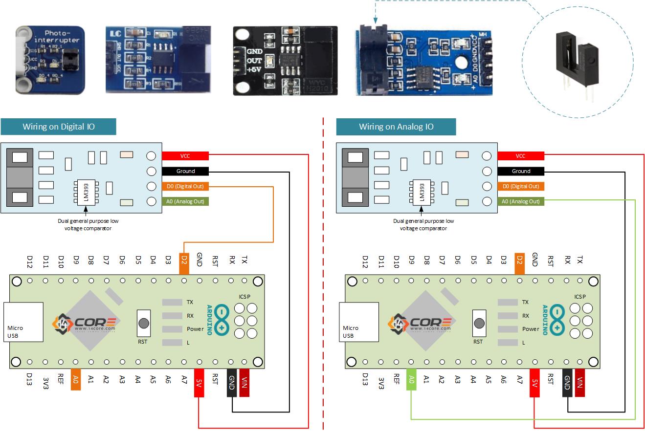
This is the photo interrupter also known as photogate, photodiode, or phototransistor. Phototransistors are specially designed transistors with the base region exposed these transistors are light sensitive, especially when an infrared source of light is being used. Phototransistors it has two leads a collector and emitter. When the light is absent the phototransistor is closed and does not allow a collector-emitter current to pass through the phototransistor open only with the presence of sufficient light.
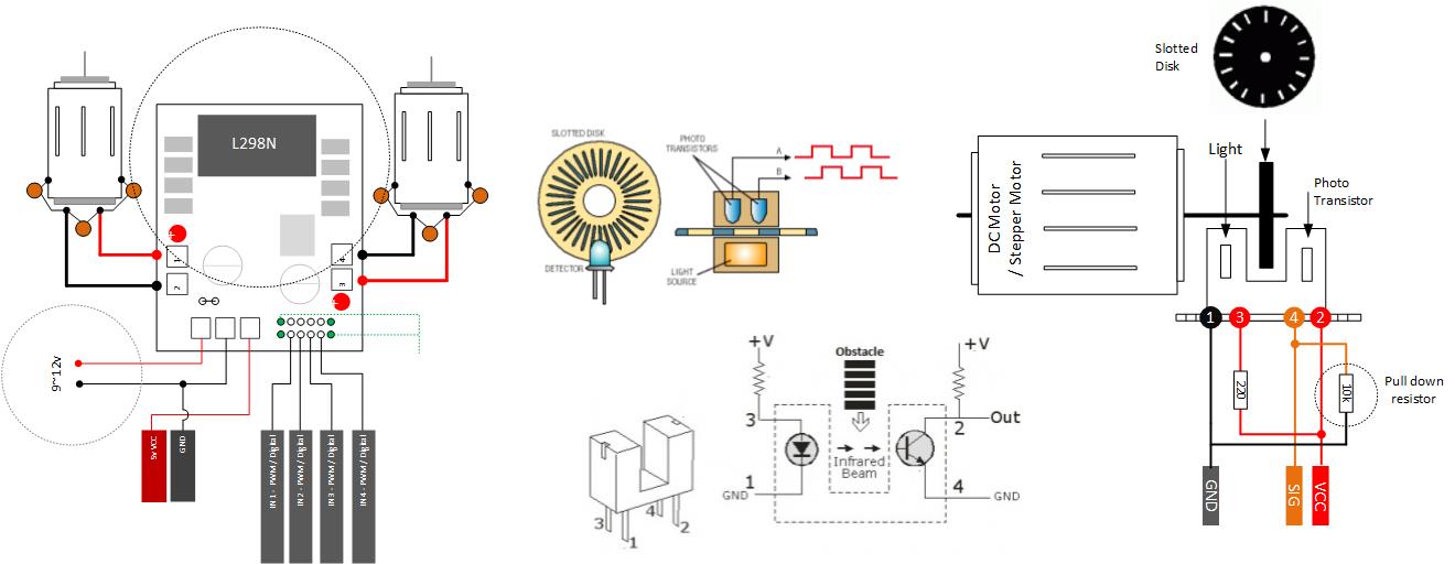
On this illustration, we will demonstrate using a dc motor with flat slotted disk attach to the motor when the motor spins the slotted disk interfere with the beam from the led to the phototransistor. The width blade affects the efficiency of the motor as it determines how long the electromagnet stays on. If you want to make your own slotted disk keep in mind that it should be dense as paper or cardboard might be semi-transparent for infrared light. Opto interrupter is a small U-shaped black plastic package which has four pins two for infrared LED on one side pin for light sensitive transistor and external connection is required. The infrared light and the photo diode are in a single package the photo-interrupter employs trans missive technology to sense obstacles existence, act as on/off switch or sense a low-resolution rotary or linear motions. The principle states that object opaque to the infrared will interrupt the transmission of light between an infrared emitting diode and a photo sensor switching from the output of HIGH state to LOW state.
Required Components
Arduino Microcontroller, ESP8266 12, 12E, ESP8266 NodeMCU, ESPDuino, WeMos, ATMEGA328 16/12, ATMEGA32u4 16/8/ MHz, ESP8266, ATMEGA250 16 MHz, ATSAM3x8E, ATSAM21D, ATTINY85 16/8 MHz (Note: The Diagram below is using NANO. If your using other MCU please refer to the respective pin-outs
MOC78XX / H206 / GP1A57HRJOOF Opto Interrupter or Module
Solder Less Bread Board
Jumper Wire / DuPont Wire
Wiring Guide
Source Code for Digital IO
1
2
3
4
5
6
7
8
9
10
11
12
13
14
15
16
17
18
19
intPinOut=2;//Set assign digital pin 2
intmyDelay=500;
voidsetup()
{
Serial.begin(9600);//Set Serial Communication
pinMode(PinOut,INPUT);//Set as INPUT
Serial.println("14CORE | Opto Interrupter Digital Out Test Code")
interrupPin is 0 or 1, for digital 3 or 5, interrupServiceRoutine functioin to run trigger ISR to run can be
LOW, RISING, or CHANGE
*/
attachInterrupt(0,currentPosition,FALLING);
}
voidcurrentPosition(){
if(digitalRead(PinIn==HIGH){position++;}//Set moving in positive direction, increment position
else
{position--;}//Set moving in nigative direction, decrement position
}
voidloop(){
Serial.println("Starting Direction Detection");
digitalWrite(PinLed,HIGH);
delay(myDelay);
digitalWrite(PinLed,LOW);
delay(myDelay);
}
Source Code for Direction Detection
In order to detect the speed of the motor, the time must be taken into account if time is recorded at each pulse from the photo-interrupter then compared to the time of the previous pulse, the motor revolutions per minute can be calculated.
1
2
3
4
5
6
7
8
9
10
11
12
13
14
15
16
17
18
19
20
21
22
23
24
25
26
27
28
29
30
31
32
33
34
35
36
37
38
39
40
41
42
intPinIn=5;//Set assign digital pin 5
intPinLed=13//Set led status indicator pin 13
intmyDelay=500;//Delay 13
volatile intposition=0;
volatile booleandirection=false;
volatile unsignedlongtime=0;
volatile unsignedintinTime;
volatile intrevPerMin;
constintspokes=2;
voidsetup()
{
Serial.begin(9600);//Set Serial Communication
pinMode(PinIn,INPUT);//Set as INPUT
pinMode(PinLed,OUTPUT);//Set as OUTPUT
Serial.println("14CORE | Opto Interrupter Direction Test Code")
We use cookie to provide you the best possible experience, this site uses cookies and by continuing to use the site you agree that we can save them on your device. Cookies are small text files which are placed on your computer and which remember your preference / some details of your visit. Our cookies don’t collect any personal information. For information, please read our Privacy Statement and Cookie Policy , which also explains how to disable this option in your browser. Cookie SettingsACCEPT
Privacy & Cookies Policy
Privacy Overview
This website uses cookies to improve your experience while you navigate through the website. Out of these cookies, the cookies that are categorized as necessary are stored on your browser as they are as essential for the working of basic functionalit...
Necessary cookies are absolutely essential for the website to function properly. This category only includes cookies that ensures basic functionalities and security features of the website. These cookies do not store any personal information.
Any cookies that may not be particularly necessary for the website to function and is used specifically to collect user personal data via analytics, ads, other embedded contents are termed as non-necessary cookies. It is mandatory to procure user consent prior to running these cookies on your website.