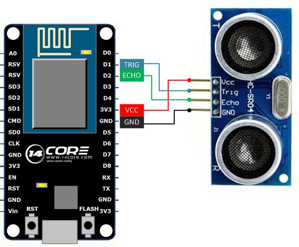
In this illustration we will going to wire the ESP8266 12E nodeMCU with Ultrasonic Raging Sensor HCSR04. As you can see the illustration below the sensor trigger pin is connected to D1 which is pin 5 in Arduino Board, and the ECHO is connected to D2 which is pin 4 in Arduino Board. However in the sketch code we are going to use the Arduino IDE to program the NodeMCU ESP8266 12E Development board if you to have a interpreter in your Arduino IDE please refer to this link.
Hardware Required
- NodeMCU ESP8266 12E Development Board
- HCSR04 Ultrasonic Raging Sensor
- Jumper Wires & DuPont Wires
- Solderless Breadboard
Wiring Diagram
Test Code
Wiring ESP8266 nodeMCU with HCSR04 Ultrasonic Sensor


HC-SR04 is a 5V device, anybody????? this circuit might work (sometimes) but it is simply wrong
There are also models which work within a range of 3.3V-5V (marked as HC-SR04+ on the backside)
use HC-SR04P as it has a wide range of operating voltage, 3-5.5V.
ese sensor no funciona bien con 3.3v.
ese lo tienes que alimentar con 5v forzosamente para que opere adecuadamente, y si funcionará con ese código pero, quizás eches a perder las GPIO si no haces la correcta acoplación de niveles lógicos.
si no quieres batallar usa el MAXBOTIX EZ-03
the sensor does not work well with 3.3v.
that you have to feed 5v necessarily to operate properly, and if it will work with that code but perhaps fuck off the GPIO if you do not the right coupled logic levels.
if you do not want troubles you most use the EZ-03 MAXBOTIX
I can confirm this code and wiring works with a logic level converter between the ESP8266 and nodeMCU. gives pretty accurate distance results
Alguien me dice si ese codigo realmente hara que mi sensor me de los datos en centi!etros o que hace ese codigo(soy nuevo) y como se si el sensor ocupa los 5 v o solo la energia fel nodemCU
Hay un cierto error en el diagrama arriba, usted necesita 5v que puede ser engancha para arriba en el usb micro cercano, antes de que usted vaya a hacer esto, lo hace seguro su fuente de NodeMCU es 5v así que usted puede conseguir 5v hacia fuera del micro USB Luego conéctelo en el Sensor VCC, GROUND (tierra común), ECHO, TRIG. :) or you can use Logic Level.
how to make nodemcu and proximity sensor worked?
Note: ESP Supply Voltage is 3.3v
You can use 5v regulator to supply your proximity sensor
ESP D1(Arduino IO Pin 5) —-> Proximity Signal
ESP GND —> Proximity Gnd
Regulator 5v – Proximity VCC
Regulator Gnd – Proxmity Gnd
Code: ————————————————
float sensor;
int monitoring;
int metalDetection = 1;
void setup(){
Serial.begin(9600);
}
void loop(){
monitoring = analogRead(metalDetection);
sensor = (float) monitoring*100/1024.0;
Serial.print(“14CORE PROXIMITY TEST”);
delay(500);
Serial.print(“Initializing Proximity Sensor”);
delay(500);
Serial.print(“Please wait…”);
delay(1000);
Serial.print(“Proximited = “);
Serial.print(sensor);
Serial.println(“%”);
if (monitoring > 250)
Serial.println(“Detected”);
delay(1000);
}
Hello everyone,
I have a strange behaviour of the sensor with an ESP8266 measuring the water volume in an IBC container.
The container has a height of 1 meter and the sensor is attached to the top of it. The ESP8266 is connected via a 2 meter cable and is in a dry housing.
The ESP8266 sends the data every 15 minutes to a webserver. The data is correct between 8 am and 8 pm on days with good condition. In the night and on rainy days the sensor sends wrong data (distance=9cm). I can’t think of any error causing this problem only on dark condition. For example today it was very rainy and I got correct values only from 11 am till 4 pm.
I will set up a second ESP 8266 and HCSR04 soon to cross-check it. Maybe someone has some thoughts on this.
Thanks.
Christian
Christian – the sensor uses sound to bounce off the object and measure the distance based on the time it takes to echo back. If you see very low results, it’s quite possible a very small amount of condensation has formed on the sensor. Temperatures tend to drop at night causing condensation, and rain means the air is near 100% humidity. Depending on your application, you may want to try a waterproof sensor such as a JSN-SR04T which may tolerate your conditions better. Good luck!
Beware of moisture on the components. The temperature usually condenses the water of the atmosphere
can i get code of this project plzz.. it very relate able to my project
help me by sharing code
Check the download link below..
Pingback:Ultrasonic Sensors
Does the pin for echo have to be a pwm pin or can it be any?
Its up to you, echo act as a pulse receiver, when pulse is transmit it goes to echo, so if you value time/measurement then use PWM, if don’t then use DPins. :)
This code shows the output to be 0 centimeters