#include <Wire.h>
#include <Adafruit_GFX.h>
#include <ESP_Adafruit_SSD1306.h>
#include "ESP8266WiFi.h"
#include "DHT.h"
#define OLED_RESET 4
Adafruit_SSD1306 display(OLED_RESET);
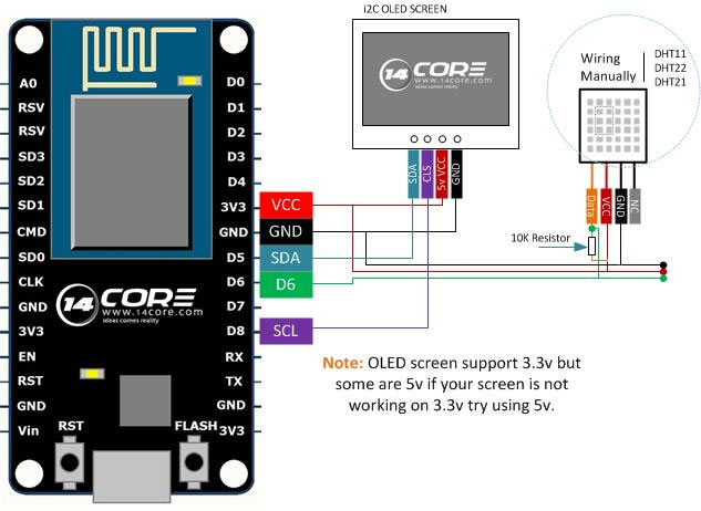
#define DHTPIN 14 // Connected to Pin D5 in NodeMCU
// Uncomment whatever type you're using!
#define DHTTYPE DHT11 // DHT 11
//#define DHTTYPE DHT22 // DHT 22 (AM2302)
//#define DHTTYPE DHT21 // DHT 21 (AM2301)
DHT dht(DHTPIN, DHTTYPE,15);
byte img [] = {
0x0, 0x0, 0x0, 0x0, 0x0, 0x0, 0x0, 0x0, 0x0, 0x0, 0x0, 0x0, 0x0, 0x0, 0x0,
0x0, 0x0, 0x0, 0x0, 0x0, 0x0, 0x0, 0x0, 0x0, 0x0, 0x0, 0xf, 0xf0, 0x0, 0x0,
0x0, 0x0, 0x3f, 0xfc, 0x0, 0x0, 0x0, 0x0, 0xff, 0xff, 0x0, 0x0, 0x0, 0x1, 0xfc,
0x3f, 0x80, 0x0, 0x0, 0x3, 0xe0, 0x7, 0xc0, 0x0, 0x0, 0x7, 0x80, 0x1, 0xe0, 0x0,
0x0, 0xff, 0x0, 0x0, 0xff, 0x0, 0x3, 0xfe, 0x0, 0x0, 0x7f, 0xc0, 0x7, 0xe2, 0x0,
0x0, 0x4f, 0xe0, 0x7, 0x80, 0x0, 0x0, 0x1, 0xe0, 0xf, 0x0, 0x0, 0x0, 0x0, 0xf0,
0x1e, 0x0, 0x0, 0x0, 0x0, 0x70, 0xe, 0x0, 0x0, 0x0, 0x0, 0x78, 0xc, 0x0, 0x0,
0x0, 0x0, 0x30, 0xc, 0x0, 0x0, 0x0, 0x0, 0x30, 0xc, 0x0, 0x0, 0x0, 0x0, 0x30,
0xe, 0x0, 0x0, 0x0, 0x0, 0x70, 0x1e, 0x0, 0x0, 0x0, 0x0, 0x70, 0xf, 0x0, 0x0,
0x0, 0x0, 0xf0, 0x7, 0x80, 0x0, 0x0, 0x1, 0xe0, 0x7, 0xe3, 0x80, 0x1, 0xc7, 0xe0,
0x3, 0xff, 0xc0, 0x3, 0xff, 0xc0, 0x0, 0xff, 0xf0, 0xf, 0xff, 0x0, 0x0, 0x20, 0xfc,
0x3f, 0x4, 0x0, 0x0, 0x0, 0x3f, 0xfc, 0x0, 0x0, 0x0, 0x0, 0xf, 0xf0, 0x0, 0x0,
0x0, 0x4, 0x0, 0x0, 0x0, 0x0, 0x0, 0x4, 0x0, 0x0, 0x0, 0x0, 0x0, 0xe, 0x0,
0x0, 0x0, 0x0, 0x0, 0xe, 0x0, 0x0, 0x0, 0x0, 0x0, 0x1f, 0x0, 0x0, 0x0, 0x0,
0x0, 0x1f, 0x0, 0x0, 0x20, 0x0, 0x0, 0x1f, 0x0, 0x0, 0x20, 0x0, 0x0, 0xe, 0x0,
0x0, 0x70, 0x0, 0x0, 0x0, 0x1, 0x80, 0x70, 0x0, 0x0, 0x0, 0x1, 0x80, 0xf8, 0x0,
0x0, 0x0, 0x3, 0xc0, 0xf8, 0x0, 0x0, 0x0, 0x3, 0xc0, 0xf8, 0x0, 0x0, 0x0, 0x3,
0xc0, 0x70, 0x0, 0x0, 0x0, 0x3, 0xc0, 0x0, 0x0, 0x0, 0x0, 0x3, 0xc0, 0x0, 0x0,
0x0, 0x0, 0x1, 0x80, 0x0, 0x0, 0x0, 0x0, 0x0, 0x0, 0x0, 0x0, 0x0, 0x0, 0x0,
0x0, 0x0, 0x0, 0x0, 0x0, 0x0, 0x0, 0x0, 0x0, 0x0, 0x0, 0x0, 0x0, 0x0, 0x0,
};
void setup() {
Serial.begin(9600);
Serial.println("DHTxx test!");
// dht begin
dht.begin();
// set display
display.begin(SSD1306_SWITCHCAPVCC, 0x78>>1);
display.display();
delay(2000);
display.clearDisplay();
}
void showTemp(float temp,float hud) {
display.drawBitmap(0, 5, img, 48, 50, 1);
display.setTextSize(1);
display.setCursor(3,0);
display.println("Temperature/Humidity");
display.setTextSize(2);
display.setTextColor(WHITE);
display.setCursor(52,10);
display.print(temp);
display.println("C");
display.setCursor(52,30);
display.print(hud);
display.println("%");
display.setTextSize(1);
display.setCursor(52,50);
display.println("14CORE.COM");
display.display();
display.clearDisplay();
void loop() {
delay(1000); // Wait a few seconds between measurements.
float h = dht.readHumidity();
float t = dht.readTemperature(); // Read temperature as Celsius
if (isnan(h) || isnan(t)) {
Serial.println("Failed to read from DHT sensor!");
return;
}
Serial.print("Humidity: "); // show in serial monitor
Serial.print(h);
Serial.print(" %\t");
Serial.print("Temperature: "); // show in serial monitor
Serial.print(t);
Serial.print(" *C \n");
showTemp(t,h); // show temp
}


Hi!
Tried your code but i get nothing when putting uploading it.
Also, the code would not compile at first, i found a unclosed bracket. But still, after upload nothing happens. Have i missed something? Using a NodeMCU, OLED with i2C and a DHT11.
The missing bracket (as i understand it);
display.clearDisplay();
}; <- Added this
void loop() {
delay(1000); // Wait a few seconds between measurements.
Check the input voltage of your OLED Screen, sometimes the OLED screen works on 5v. you can achieve the 5v by hooking up 1 jumper to get 5v. note: ground should be common ground.
I’ve tried the screen at 3.3v with a arduino and som other codes on the NodeMCU and then it works. But will try the 5 volt anyway. Maybe it aint sufficient with the setup. It’s spec at 3-5 volt.
Other thoughts;
#include
#include
#include
#include “ESP8266WiFi.h”
Shouldn’t it be;
#include “Wire.h”
#include “Adafruit_GFX.h”
#include “ESP_Adafruit_SSD1306.h”
#include “ESP8266WiFi.h”
or does it not matter?
This probably fixed it, got the pins wrong. For me the working combination was;
DHT: D5
SCL: D1
SDA: D2
So sorry for all other mumbling above :)
Thanks for coding and fixing coding. But surprise for me rook. I have found that I have to use an 4,7 KOhm resistor between VCC and signal from DHT11. And it works . But again I am an rook
You are right. Actually the wiring diagram is wrong because the 10kOhm resistor must be connectet between +Vcc and DATA pin of DHTxx sensor. So in your case, addind 4.7kOhm got the same result.
With resistor between GND and DATA I guess nobody will get it works!!!
In file included from C:\Users\Pradeep\Documents\Arduino\NodeMCUESP8266_OLED_DHT22\NodeMCUESP8266_OLED_DHT22.ino:1:0:
C:\Users\Pradeep\Documents\Arduino\libraries\SPI/SPI.h:16:26: fatal error: avr/pgmspace.h: No such file or directory
#include
^
compilation terminated.
Multiple libraries were found for “SPI.h”
Used: C:\Users\Pradeep\Documents\Arduino\libraries\SPI
Not used: C:\Users\Pradeep\AppData\Local\Arduino15\packages\esp8266\hardware\esp8266\2.3.0\libraries\SPI
exit status 1
Error compiling for board NodeMCU 1.0 (ESP-12E Module).
hi! your using multiple SPI library, you need to remove some unused SPI library in your arduino IDE . make it sure that Adafruit_GFX.h is available in your list.
> C:\Users\Pradeep\Documents\Arduino\libraries\SPI
You can use this library from U8G >
http://www.14core.com/wiring-the-128×64-1-3-inch-oled-display-on-4-wire-3-wire-i2c-interface/
Please, there should be a mistake in Wirin Diagram;
The 10 kOhm resistor should be connected from DHTxx DATA pin to VCC pin, not to GND.