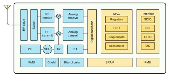
The ESP8266 module has a preprogrammed firmware which support the serial interface communication by controlling using AT commands. The ESP8266 chip was develop by ESPRESSIF System, a smart connectivity platform or ESCP that provides high performance, high integration wireless SOCs, the chip designed for space and power constrained mobile platform. The ESP8266 provides unsurpassed ability to embed Wifi capabilities within other system, or to the application, and minimal space requirement. The has integrated 802.11 b/g/n protocol, WiFi Direct P2P, soft-AP Integrated TCP/IP protocol stack, 32bit processor (80MHz), 512KB SPI Flash, G4KB SRAM, 96KB DRAM, and the GPIO pins.
The ESP8266 Block Diagram
Required Components
ESP8266 Version 1
USB TTL UART Bridge CP2102 or FTDI TTL UART (Drivers can be downloaded here)
Solder Less Bread Board
Jumper Wire / DuPont Wire
Before we will going to flash the ESP8266 Board we need two files that can be downloaded below.
1. The ESP8266 Firmware 9.5.0
2. Chip Flasher Tool
Wiring diagram
Below are the wiring the ESP8266 with CP2102 USB TTL UART we can also use the FTDI TTL UART for this procedure.
Flashing The ESP8266 Procedure
After flashing the ESP8266 Firmware, the settings will be changed and default baud rate will be 9600 and you can modified it using command AT+CIOBAOUD using Putty you can now remote the GPIO-0 from the ground and pressed RESET button then close the flasher tool application.
For verify the functionality of ESP8266 you used PuTTY application by opening the terminal and type AT.
Download ESP8266 Datasheet here | PDF
Download ESP8266 Flash Tool | Zip
Download ESP8266 Binary File (BIN) Version 9.5.0 | Zip


