The PWM or Pulse width Modulation can be used on the Arduino is several ways. In this guide explain how PWM work and techniques, as well as how to use the PWM registers directly to the Arduino board and control over the duty cycle and frequency. This illustration focuses on the ATMEGA168 and ATMEGA328.
If you are not familiar with pulse with modulation read and see the tutorial briefly, a Pulse width modulation signal is a digital square wave, where the frequency is constant, but that fraction of the time the signal is on the duty cycle can be varied between 0 and 100 percent.
The Pulse width Modulation Examples
PWM can be used in several ways.
1. Dimming a LED
2. Providing an analog output if the digital output is filtered. It will provide an analog voltage between 0 percent and 100 percent.
3. Generating audio signals.
4. Providing variable speed control for motors.
5. Generating a modulated signal, for example to drive an infrared LED for a remote control.
Simple PWM on AnaloWrite
The Arduino programming language can makes PWM very easy to use simple call the function analogWrite(pin, dutyCycle), where dutyCycle can be valued from 0 to 255, and the pins is one of the PWM pins 3,5,6,9,10, and 11 please see the ATMEGA168, ATMEGA328 Pinouts. The analogWrite function provides a simple interface to the hardware PWM, but does not provide any control over frequency. Note that despite the function name, the output will be a digital signal is often referred to as a square wave.
Bit PWM (Pulse Width Modulation)
You can “manually” implemented PWM on any pin by repeatedly turning the pin and OFF for the desired times.
Example:
This ides and technique has the advantage that it can use any digital output pin. I addition, you have full control the duty cycle and frequency. One major disadvantage is that any interrupts will affect the timing, which can cause considerable jitter unless you disable the interrupts. A second disadvantage is you can’t leave the output running while the processor does sometime else. It is difficult to determine the appropriate constants for a particular duty cycle and frequency unless you either carefully count the cycles or tweak the values while watching on the oscilloscope.
How to use the ATMEGA PWM Register Directly
The ATMEGA 168P/32P Chip has 3 Pulse Width Modulation timer, controlling 6 PWM output. By manipulating the chip timer registers directly, we can obtain more control than the analogWrite function provides.
The AVR ATMEGA328P Datasheet provide a detailed description of the PWM timers, but the datasheet sometimes can be difficult to understand, due to the many different control and output modes of the timers.
The ATMEGA 168/328 Timers
The ATMEGA328P has three timers known as Timer0, Timer1, and the Timer2. Each timer has two output compare to the registers that control the PWM (Pulse Width Modulation) for the timers there are two output, when the timer reaches the compared register value, the corresponding output is toggled. The two output for each timer will normally have the same frequency, but can have different duty cycles (depending on the respective output compare to register).
The timers are complicated by several different modes. The main PWM modes are Fast PWM and Phase-Correct PWM, which will be described down below, the timer can either run from 0 to 255, or from 0 to a fixed value. The 16-bit timer 1 has additional modes to support timer values up to 16bits. Each output can be also be inverted.
Timers can be also generated interrupts on overflow and or match against either output compare register, but that beyond the scope of this illustration. Timer Register several registers are used to control each timer. The Timer/Counter control register TCCRnA and TCCRnB holds the main control bits for the timer. Note that TCCRnA and TCCRnB do not correspond the output A and B. Theses registers hold several groups of bits.
• WGM (Wave Generation Mode bits ): These control the overall mode of the timer.(These bits are split between TCCRnA and TCCRnB)
• CS (Clock Select Bits): These control the clock prescaler (A prescaler is an electronic counting circuit used to reduce a high frequency electrical signal to a lower frequency by integer division.)
• COMnA (Compare Match Output A Mode Bits): These enabled/disabled/invert output A
• COMnB (Compare Match Output B Mode Bits): These enabled/disabled/invert output B
The OCRnA and OCRnB (Output Compare Registers) set the level at which output A and B will be affected. When the timer value matches the register value, the corresponding output will be modified as specified by the mode.
The bits are slightly different for each timer, kindly see the datasheet for the details. Timer 1 is a 16 bit timer and has additional modes. Timer 2 has different prescaler values.
The Fast Pulse width Modulation
In Pulse Width Modulation mode, the timer relatedly counts from 0 to 255. The output turns on when the timer is at 0, and turns off when the timer matches the output compare register. The higher the value in the output compare register, the higher the duty cycle. This mode is known as Fast Pulse Width Modulation Mode. The following diagram shows the output for two particular values of OCRnA and OCRnB these both outputs have the same frequency matching of a complete timer cycle.
The Fast Pulse width Modulation Mode
The following code below sets up the fast PWM on pin 3 and 11 Timer 2. To summarize the register settings, setting the waveform generation mode bits WGM to 011 selects fast PWM. Settings the COM2A bits and COM2B bits to 10 provides non-inverted PWM for outputs A and B. Settings the CS bits to 100 sets the prescaler to divide the clock by 64. Since the bits are different for the different timers, please see the datasheet for the right values. The output compare registers are arbitrarily set to 180 and 50 to control the PWM duty cycle of output A & B. you can modify the registers directly instead of using pinMode, but you need to set the pins to output.
• On the Arduino Board, The values provide
• Output A Frequency: 16 MHz / 64 / 256 = 976.5625 Hz
• Output A Duty Cycle: 180+1 / 256 = 70.7%
• Output B Frequency: 16 MHz / 64 / 256 = 976.562 Hz
• Output B Duty Cycle: 50 + 1 / 256 = 19.9%
The output is the 16 MHz system clock frequency, divided by the prescaler value 64, divided by the 256 cycle and it takes the timer to wrap around. That fast Pulse width Modulation holds the output high one cycle longer than the compare register values.
The Phase-Correct Pulse width Modulation
The second PWM mode is named phase-correct Pulse width Modulation. In this mode the timer counts from 0 to 255 and the back to 0. The output turns off as the timer hits the output compare register values on the way up, and turn down on as the timer hits the output frequency will be approximately half of the value for the fast Pulse width Modulation mode, because the timer runs both up and down.
The Phase-Correct Pulse width Modulation Example
The illustration below sets up phase-correct Pulse width Modulation on pin 3 and 11 timer 2. The waveform generation mode bits WGM are set to 001 for phase-correct Pulse width Modulation. The other bits are the same as for the fast Pulse width Modulation.
On the Arduino Board, These values provide
- OUTPUT A FREQUENCY: 16 MHz / 64 / 255 / 2 = 490.196 Hz
- OUTPUT B DUTY CYCLE: 180 / 255 = 70.6 Percent
- OUTPUT A FREQUENCY: 16 MHz / 64 / 255 / 2 = 490.196 Hz
- OUTPUT B DUTY CYCLE: 50 / 255 = 19.6 Percent
The Phase-Correct Pulse width Modulation divided by the frequency by two compared to FAST PULSE WIDTH MODULATION, because the timer goes both up and down, the frequency is divided by 255 instead of 256, and the duty cycle calculations does not adding ones as for FAST PWM. See the illustration below.
Differ the size of the timer top limit: FAST Pulse width Modulation
Both fast and phase-correct Pulse width Modulation have an additional mode that provide control over the output frequency. By this mode, the timer counts from 0 to OCRA value of output compare register A, rather than 0 to 255. This provide much more control over the output frequency that the previous modes, for more frequency control used the 16 bit timer 1.
In this mode, only output B can be used for Pulse width Modulation the OCRA cannot be used both as the top value and the PWM compare value. There is a special case mode the TOGGLE OCnA on compare match that will toggle output A at the end of each cycle, generating a fixed 50 percent duty cycle and half frequency.
The timer resets when it matches OCRnA, yielding a faster output frequency for OCnB than in the previous diagram. Note how OCnA toggle once for each timer reset.
The Fast Pulse width Modulation with OCRA top
The following code illustrated below sets up fast Pulse width Modulation on pin 3 and 11 timer 2, using OCR2A as the top value for the timer. The waveform generates mode bits WGM are set to 111 for fast PWM with OCRA controlling the top limit. The OCR2A top limit is arbitrarily set to 180 and the OCR2B compare register is arbitrarily set to 50. OCR2A mode is set to toggle on compare Match by setting the COM2A bits to 01.
On the Arduino Board, These values provides.
- OUTPUT A FREQUENCY: 16 MHz / 64 / (180+1)/2 = 690.6 Hz
- OUTPUT B FREQUENCY: 50 Percent
- OUTPUT A FREQUENCY: 16 MHz / 64 / (180+1) = 1381.2 Hz
- OUTPUT B FREQUENCY: (50+1) / (180+1) = 28.2 %
In this example the timer goes from 0 to 180, which takes to 181 clock cycles, the output frequency is divided by 181. Output A has half the frequency of Output B because the Toggle on Compare Match mode toggles Output A once each complete timer cycle.
Differ the timer top limit: Phase-correct Pulse width Modulation
The timer be configured in phase-correct Pulse width Modulation mode to reset when it reaches OCRnA. Phase-Correct PWM width OCRA top the following code fragment sets up phase-correct PWM on pin 3 and 11 Timer 2, using OCR2A as the top value for the timer. The waveform generation mode bits WGM are set to 101 for phase correct Pulse width Modulation OCRA controlling the top limit. The OCR2A top limit is arbitrarily set to 180, and the oCR2B compare register is arbitrarily set to 50. OCR2A mode is set to toggle on compare match by setting the COM2A bit to 01.
On the Arduino Board, These values provides:
- OUTPUT A FREQUENCY: 16 MHz / 64 / 180 / 2 / 2 = 347.2 Hz
- OUTPUT A DUTY CYCLE: 50 Percent
- OUTPUT B FREQUENCY: 16 MHz / 64 / 180 / 2 = 694.4 Hz
- OUTPUT B DUTY CYCLE: 50 / 180 = 27.8 %
On this example, the timer goes from 0 to 180 and back to 0, which takes 360 clock cycle. Everything is divided by 180 or 360, unlike the fast Pulse width Modulation case, which divided everything by 181. You may noticed that fast Pulse width Modulation and Phase-Correct Pulse width Modulation seem to be off-by-one with respect to each other, dividing by 256 versus 255 and adding one in various places.
Suppose the timer is set to fast Pulse width Modulation mode and is set to count up to an OCRnA value of 3. The timer will take on the values 012301230123. There are 4 clock cycle in each timer cycle. The frequency will be divided by 4, not 3. The duty cycle will be multiple of 25 percent since the output can be high for 0,1,2,3 or 4 cycle out of the four. If the timer counts up to 255, there will be 256 clock cycles in each timer cycle, and duty cycle will be a multiple of 1/256. To summarize, the FAST PWM divides by N+1 where N is the maximum timer value either OCRnA or 255.
Consider the phase-correct Pulse width Modulation mode with the timer counting up to an OCRnA value of 3. The timer values will be 012321012321… There are 6 clock cycle in each timer cycle 012321. The frequency will be divided by 6. The duty cycle will be multiple of 33 percent since the output can be high for 0, 3, 4, or 6 of the 6 cycle. If the timer counts up to 255 and back down there will be 510 clock cycle in each timer cycle, and duty cycle will be a multiple of 1/255. The phase-correct Pulse width Modulation divided by 2N, where N is the maximum timer value.
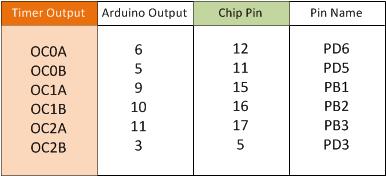
The second important timing difference compare to fast Pulse width Modulation holds the output high for one cycle longer that the output compare register value. The fast PWM counting to 255, the duty cycle can be from 0 to 256 cycles, but the output compare register can only hold a value from 0 to 255. What happens to the missing values? The fast Pulse width Modulation mode keeps the output high for N-1 cycles when the output compare register is set to N so an output compare register value of 255 is 100 percent duty cycle, by an output compare register value of 0 is not 0 percent duty cycle but 1/256 duty cycle. This is unlike phase-correct Pulse width Modulation where a register value of 255 is 100 percent duty cycle and a value of 0 is a 0% duty cycle. Timers and the Arduino; The Arduino supports PWM on a subnet of its output pins. It may be immediately obvious which timer control which output, but the following table will clarify the situation. It provide for each timer output the output pins.
On the ATMEGA168 and ATMEGA328 Chip there is some initialization of the timer. The chip initializes the prescaler on all three timers to divide the clock by 64. Timer 0 is initialized to FAST Pulse width Modulation, while TIMER 1 and TIMER 2 is initialized to Phase Correct PWM.
The Arduino IDE on ATMEGA168 and ATMEGA328 uses TIMER 0 internally for the milis() and delay() functions, note that changing the frequency of this timer will cause those functions to be erroneous. Using the Pulse width Modulation outputs is safe if you don’t change the frequency.
The analogWrite(pin, duy cycle) function sets the appropriate pin to Pulse width Modulation and sets the appropriate output compare register to duty cycle with the special case for duty cycle of 0 on TIMER0. The digitalWrite() function turn off PWM output if called on timer pin. The code is wiring_analog.c and wiring_digital.c
If you use analogWrite(5, 0) you get a duty cycle of 0 percent even through pin 5 timer (TIMER0) is using fast Pulse width Modulation. When a fast PWM value of 0 yields a duty cycle of 1/256 as explained earlier, that analogWrite “Cheats”; it has special-case code to explicitly turn off the pin when called on TIMER0 with duty cycle of 0. As a consequency, the duty cycle of 1/256 is unavailable when you use analogWrite on TIMER0, and there is a jump in the actual duty cycle between values of 0 and 1.
Some other ATMEGA168 and ATMEGA328 development board use different AVR processors with similar timers. The Arduino MEGA uses the ATMEGA2560 , which has five 16-bit timers with 4 output each and two 8-bit timers with 2 output each. Only 15 of the PWM output are supported by the Arduino wiring library.
An OC oscilloscope is very handy for debugging Pulse Width Modulation. If you don’t have, Use your sound card and a program such as XOSCOPE.
Credit to Arduino.cc |


