 What is a Relay?
A Relay is a electronic operated switch, relay’s uses an electromagnet mechanical to operate the switch and provide electrical isolation between two circuits. Is this lab project we don’t need to isolate one circuit from other, will going to use ARDUINO UNO to control the 5v Relay. will going to make a simple circuit to demonstrate & identify the NO(Normally Open) and NC(Normally Closed) to the terminal of the relay.
Electronic Parts Required
- 1x 14Core Arduino Uno Compatible / Arduino Uno R3
- 2x 220 Ohm Resistor
- 1x 1-4 Channel Relay Module
- 2x LED
- Jumber Wires
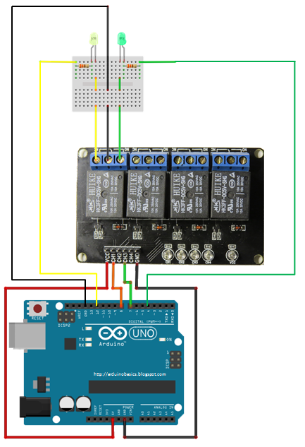
Connections:
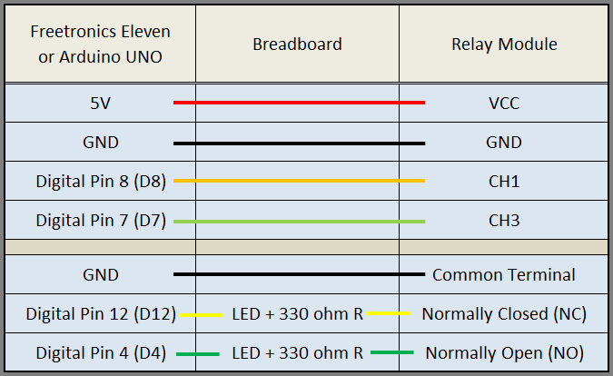
The red LED light on the Relay turns On while the power is up via the VCC pin. When power is up to one of the channel, the green light will on, then the other relay will switch from NC to NO. When power is down from the channel pin the relay will shutoff to NC from NO. This code we see that power is declared to both LED in the setup() function. When power is down going into channel 1 pin, the yellow LED will be On and the green LED will be off, because there is a break in the circuit for the green LED, When power is up going into Channel 1 the relay will switch from NC to NO closing the circuit for the green LED and open the circuit for the yellow LED. the LED Green will on and the yellow LED will off.

Download the source code here > 14core_relay_led_code


Pingback:Using Password Access Control on Matrix Keypad and Relay | 14Core.com