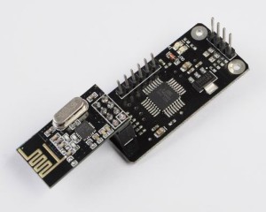
How it works?
- This module use I2C/TWI Communication protocol which simplifies the nRF24l01 communication process stable, thus users no need to understand the communication process of nRF24l01, it improves the efficiency of project development.
- This module will be use as a slave of I2C/2WI at the address 35
- It has a smooth bidirectional communication and no discernable at the slave or the master.
- It has maximum transmission distance can reach to 70m it defends on the module you use.
- nRF24l01 communication protocol will reduce the signal lost.
- 12C/TWI protocol simplifies the communication line.
- Perfectly compatible on Arduino.
- This module can be use in Robot Control System, Remote Control. Etc, this device is not recommended for life protection, it is using wireless radio communication may provide a radiation.
- This device operates on 5v and it has no short-circuit protection, so you must be careful with polarity.
- Hold time of module receiving data: 2s
- Hold time of module transmitting data: 300s
- Transfer Rate: 50Byte / S (Theoretical Value)
- I2C/TWI Address: 0x47 (decimal 35)
- nRF24l01 Address: 0x34,0x43,0x10,0x01 – from low to high
Tested Modules
nRF24l01 Version 1 / Communication range up to: 70 meter at open space
nRF24l01 Version 2 / Communication Range up to : 100 meter at open space
nRF24l01 Version 2 Plus 2.4 GHz SMA (SubMiniature version A) Antenna / Communication Range up to : 300 meter at open space
Testing on progress : nRF24l01 Version 2 with On board Signal Amplifier Plus 2.4 GHz SMA (SubMiniature version A) Antenna / Communication Range up to : 1100 meter at open space.
Setup & Implemetation Guide
- The Microcontroller reads the data, It means the MCU reads the data of the module, after the module receives the from nRF24l01 it will be save and process by the master module to read the status led will shown in module.
- Free mode ( MCU writes the data or NRF24l01 write the data) if the nRF24l01 module and the master I2C/TWI cannot do any operation when the Led Out / In is OFF.
There possible for the module operate to Free Mode:
- The clock of module data send reaches to maximum.
- Module sent data successfully.
- MCU receives data from the module.
- Free status is beyond the hold time.
- Module Status is Busy Mode : When module receives the data which has sent from master then jumps intro the “BUSY STATUS”, and send a data to another module periodically while waiting for a response signal to another module. After a period of time the (module transmit data host time there is still no answer module will jump to free mode automatically if its has received the response signal, it can also jump to a free mode( LED OUT light of module is on)
nRF24l01 Communication Diagram
MCU sends address to the module, and the module will response a signal if returned data is 0x47, indicating that reading data is successful. The MCU can read a data with 1 byte size every time.
The Microcontroller will send the address of 1byte data to the module will become busy mode state then the stop bit occur. if the process is busy mode automatically it will send the data again. When the module is in IDLE the address which is read by the master transceiver is always 0x47 and when Microcontroller receives the data we need to filter the 0x47 at decimal number 71, otherwise it will encounter an error.
The nRF24l01 Communication Module Shield
Master / Transmitter Arduino Sketch Code
[crayon-679f26dd0b962757165281/]
Slave / Receiver Arduino Sketch Code
[crayon-679f26dd0b96a497314178/]
Download the Source Codes Here | Zip