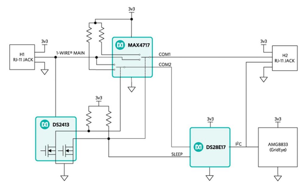
This is the MAXREFDES131 an IR array sensing device solution module. This device is mainly driven by 2 components onboard, the Panasonic AMG8833 Grid-Eye and Maxim (DS28E17) a 1 wire-to-i2c master bridge and a dual channel addressable switch along with the MAX4717 dual-SPDT analog shift allows enumeration of units on the 1 wire bus. In addition, all units can be put to sleep or individually selected one enumerated, reducing the power consumption. This system is capable of counting people that pass to the sensor base on heat registers and detecting gestures while tethered up to 100m along the 1-wire bus. This board has RJ11 connectors for easy daisy-chained setup up to 10 devices using 1 wire network bus. The RJ11 Jack, for interfacing to the hardware and daisy chaining units together. MAX4717 comes up with COM1 disconnected from the 1 wire bus and COM2 connected allowing the host to see the first DS28E17 on the bus. The DS2413 allows the host to connect or disconnect downstream units of daisy-chained MAXREFDES131 units.
MAXREFDES131# System Design Diagram
MAXREFDES132# is a 1-WIRE Shield Design for Arduino UNO (Arduino Form-Factor Pinout). This device provides a convenient platform for interfacing with 1-Wire Bus devices for ease of implementations. This device is integrated with DS2484 i2C to 1 WIRE master or (Bit-bang) master on D2 of the Arduino form-factor pinout. Both masters are support by the Mbed, OneWire, and Arduino with OneWire Code Library. The DS2484 is driven by MAX3394E two-channel bidirectional level translator provides a perfect match for 5v and 3.3v platform using the IOREF pin of the Arduino. See below the System Block Diagram.
MAXREFDES132# System Design Diagram
DS2484 an i2C to Wire Bridge device a single channel 1-wire master with adjustable timing sleep mode feature. This device interface directly to standard 100KHz max ~ 400KHz mas fast i2c masters to perform protocol conversion between the i2C master to any downstream 1 wire slave devices. Relative any attached 1 wire slave device. This device is a 1 wire master with adjustable timer discharge to any host processor from generating timer-critical 1-WIRE waveforms, subsidiary both standard and overdrive 1-WIRE communication speeds. The 1-WIRE bus can be powered down under software control, the dual-voltage operation can be operate on different operating voltage on the i2C and 1-WIRE side. Pullup features support 1-WIRE power delivery to 1-WIRE device such as EEPROMs and SENSORS. The DS2484 can be turn to sleep mode where power consumption is minimal.
Required Component
- Arduino IDE | AtmelStudio
- Arduino Microcontroller, NodeMCU, Teensy Board, TeensyDuino, ESP8266 12, 12E, ESP8266 NodeMCU, ESPDuino, ATMEGA328 16/12, ATMEGA32u4 16/8/ MHz, ESP8266, ATMEGA250 16 MHz, ATSAM3x8E, ATSAM21D, ATTINY85 16/8 MHz Note: The Diagram below is using NANO. (please refer to each MCU’s respective pin-outs)
- MAXREFDES132# | MAXREFDES131#
- Jumper Wire / DuPont Wire
Optional if you are not using MAXREFDES132# Shield
- DS2484 Single-Channel 1-Wire Master
- 10k Ohms Resistor
- 2.2k Resistor
- PCB
Wiring Guide
Grid Eye Demo Software
Grid Eye Single Device
1 2 3 4 5 6 7 8 9 10 11 12 13 14 15 16 17 18 19 20 21 22 23 24 25 26 27 28 29 30 31 32 33 34 35 36 37 38 39 40 41 42 43 44 45 46 47 48 49 50 51 52 53 54 55 56 57 58 59 60 61 62 63 64 65 66 67 68 69 70 71 72 73 74 75 76 77 78 79 80 81 82 83 84 85 86 87 88 89 90 91 92 93 94 95 96 97 98 99 100 101 102 103 104 105 106 107 108 109 110 111 112 113 114 115 116 117 118 119 120 121 122 123 124 125 126 127 128 129 130 131 132 133 134 135 136 137 138 139 140 141 142 143 144 145 146 147 148 149 150 151 152 153 154 155 156 157 158 159 160 161 162 163 164 165 166 167 168 169 170 171 172 173 174 175 176 177 178 179 180 |
#include <OneWire.h> //Download the library below #include <OWGridEye.h> //You can download the library below using namespace OneWire; using namespace RomCommands; void print_rom_id(RomId & romId); void gridEyeFx(OWGridEye & owGridEye); DS2484 owm; void setup() { Serial.begin(115200); while(!Serial); Serial.println("Starting Demo"); Serial.println(); OneWireMaster::CmdResult result = owm.begin(); if(result != OneWireMaster::Success) { Serial.println("Failed to initialize OneWire Master"); Serial.println("Ending Program"); while(1); } } void loop() { OneWireMaster::CmdResult owResult; SearchState searchState; MultidropRomIterator selector(owm); OWGridEye owGridEye(selector); DS2413 owSwitch(selector); bool ds2413Found = false; bool ds28e17Found = false; owResult = owm.OWReset(); if(owResult == OneWireMaster::Success) { //Find DS2413 searchState.findFamily(OWGridEye::DS2413_FAMILY_CODE); owResult = OWNext(owm, searchState); if(owResult == OneWireMaster::Success) { Serial.print("\nROM ID = "); print_rom_id(searchState.romId); if(searchState.romId.familyCode() == OWGridEye::DS2413_FAMILY_CODE) { //ensure DS28E17 and GridEye are connected to bus owSwitch.setRomId(searchState.romId); owSwitch.pioAccessWriteChAB(2); //let GridEye object know what the DS2413 ROM ID is owGridEye.setOWSwitchRomId(searchState.romId); ds2413Found = true; } else { Serial.println("Failed To Find DS2413"); } } //Find DS28E17 searchState.findFamily(OWGridEye::DS28E17_FAMILY_CODE); owResult = OWNext(owm, searchState); if(owResult == OneWireMaster::Success) { Serial.print("\nROM ID = "); print_rom_id(searchState.romId); if(searchState.romId.familyCode() == OWGridEye::DS28E17_FAMILY_CODE) { //let GridEye object know what the DS28E17 ROM ID is owGridEye.setI2CBridgeRomId(searchState.romId); ds28e17Found = true; } else { Serial.println("Failed To Find DS28E17"); } } if(ds2413Found && ds28e17Found) { Serial.println(); Serial.println("OWGridEye Found"); gridEyeFx(owGridEye); } else { Serial.println("Failed To Find OWGridEye Sensor"); } } else { Serial.println("No OneWire Devices On Bus"); } delay(3000); } //********************************************************************* void print_rom_id(RomId & romId) { //print the rom number Serial.println(); for(uint8_t idx = 0; idx < RomId::byteLen; idx++) { if(romId[idx] < 16) { Serial.print("0x0"); Serial.print(romId[idx], HEX); Serial.print(" "); } else { Serial.print("0x"); Serial.print(romId[idx], HEX); Serial.print(" "); } } Serial.println(); } //********************************************************************* void gridEyeFx(OWGridEye & owGridEye) { if(owGridEye.connectGridEye() == OWGridEye::Success) { Serial.println("GridEye Connected"); //wait long enough for sample delay(100); int16_t pixelTemperature[64]; float pixelTemperatureF; uint8_t idx, idy; OWGridEye::CmdResult result = owGridEye.gridEyeGetFrameTemperature(pixelTemperature); if(result == OWGridEye::Success) { Serial.println(); for(idx = 0; idx < 8; idx++) { for(idy = 0; idy < 8; idy++) { pixelTemperatureF = fAMG_PUB_CMN_ConvStoF(pixelTemperature[idx*8 + idy]); Serial.print(pixelTemperatureF, 2); Serial.print(" "); } Serial.println(); } Serial.println(); if(owGridEye.disconnectGridEye() == OWGridEye::Success) { Serial.println("GridEye Diconnected"); } else { Serial.println("GridEye Diconnect Failed"); } } else { Serial.println("GridEye Access Failed"); } } else { Serial.println("GridEye Connect Failed"); } } |
Downloads
- Download MAXREFDES131 Arduino OneWire Library | Zip
- Download MAXREFDES131 Arduino OWGridEye Library | Zip
- Download MAXREFDES131 Arduino Firmware | Download Link
- Download MAXREFDES131# Datasheet | PDF
- Download MAXREFDES131# Schematics | PDF
- Download MAXREFDES131DemoV1.00 | Download Link
- Download MAXREFDES131 Arduino Firmware | Download Link
- Download MAXREFDES132 Schematics | PDF
- Download MAX3394E two-channel Datasheet | PDF
- Download DS2484 an i2C to Wire Bridge Datasheet | PDF