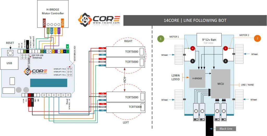
This is the 14CORE Design Line Following robot which is capable of detecting lines and follow it. This robot uses TCRT5000 Sensor which is capable of emitting dark color lines. The TCRT5000 are reflective sensors which include an infrared emitter and photo-transistor in a leaded package which blocks visible light. For more details about the sensor please refer to the product datasheet below. If your new to H-BRIDGE / Motor controller just follow also this link L293D / L298N.
Required Components
- Arduino Microcontroller / Teensy (Please refer to the pin-out diagram)
- L298N / l293D Motor Controller
- Smart Robot Car Kit / Build your own Kit
- 2 or 4 Gear-head Motor or Stepper Motor (for wiring the stepper motor follow this link)
- TCRT5000 Module
- TCRT5000 Sensor (for manual construction of the sensor)
- 10k Resistor (for manual construction of the sensor)
- 510 Ohms (for manual construction of the sensor)
- Jumper Wire / DuPont Wire
- Bread-board
Wiring Diagram
Source Code for 4 TCRTS5000
|
1 2 3 4 5 6 7 8 9 10 11 12 13 14 15 16 17 18 19 20 21 22 23 24 25 26 27 28 29 30 31 32 33 34 35 36 37 38 39 40 41 42 43 44 45 46 47 48 49 50 51 52 53 54 55 56 57 58 59 60 61 62 63 64 65 66 67 68 69 70 71 72 73 74 |
#define ENA_PIN 5 // ENA attach to pin5 #define ENB_PIN 6// ENB attach to pin6 #define MOTOR_L_1 8 // MOTOR_L_1 attach to pin8 #define MOTOR_L_2 9 // MOTOR_L_1 attach to pin9 #define MOTOR_R_1 10 // MOTOR_R_1 attach to pin10 #define MOTOR_R_2 11 // MOTOR_R_1 attach to pin11 #define FORWARD 0 //define forward=0,car move forward #define BACK 1 //define back=1,car move back #define LIGHT_LEFT_1_PIN A0 //attach the left first Tracking module pinA0 to A0 #define LIGHT_LEFT_2_PIN A1 //attach the left second Tracking module pinA0 to A1 #define LIGHT_MIDDLE_PIN A2 //attach the module Tracking module pinA0 to A2 #define LIGHT_RIGHT_1_PIN A3 //attach the right second Tracking module pinA0 to A3 #define LIGHT_RIGHT_2_PIN A4 //attach the right first Tracking module pinA0 to A4 #define SPEED 180 //define SPEED=180,it is the rotate speed of motor unsigned char flag = 3; unsigned char angle = 90; void setup() { /* set below pins as OUTPUT */ pinMode(ENA_PIN, OUTPUT); pinMode(ENB_PIN, OUTPUT); pinMode(MOTOR_L_1, OUTPUT); pinMode(MOTOR_L_2, OUTPUT); pinMode(MOTOR_R_1, OUTPUT); pinMode(MOTOR_R_2, OUTPUT); } void loop() { if (analogRead(LIGHT_LEFT_1_PIN) > 758) //if read the value of the left first Tracking module pinA0 is more than 758 flag = 1;//flag=1 else if (analogRead(LIGHT_LEFT_2_PIN) > 758) //if read the value of the left second Tracking module pinA0 is more than 758 flag = 2; else if (analogRead(LIGHT_MIDDLE_PIN) > 758) //if read the value of the module Tracking module pinA0 is more than 758 flag = 3; else if (analogRead(LIGHT_RIGHT_2_PIN) > 758) //if read the value of the right second Tracking module pinA0 is more than 758 flag = 4; else if (analogRead(LIGHT_RIGHT_1_PIN) > 758) //if read the value of the right first Tracking module pinA0 is more than 758 flag = 5; else flag = 6; CAR_move(FORWARD, SPEED, SPEED); //car move forward with speed 180 } void CAR_move(unsigned char direction, unsigned char speed_left, unsigned char speed_right) { switch (direction) { //car move forward with speed 180 case 0: digitalWrite(MOTOR_L_1, HIGH); digitalWrite(MOTOR_L_2, LOW); //left motor clockwise rotation digitalWrite(MOTOR_R_1, HIGH); digitalWrite(MOTOR_R_2, LOW); break; //right motor clockwise rotation //car move back with speed 180 case 1: digitalWrite(MOTOR_L_1, LOW); digitalWrite(MOTOR_L_2, HIGH); digitalWrite(MOTOR_R_1, LOW); digitalWrite(MOTOR_R_2, HIGH); break; default: break; } analogWrite(ENA_PIN, speed_left); //write speed_left to ENA_PIN,if speed_left is high,allow left motor rotate analogWrite(ENB_PIN, speed_right); //write speed_right to ENB_PIN,if speed_right is high,allow right motor rotate } |
Source Code for 3 TCRT5000 (Left | Center | Right)
|
1 2 3 4 5 6 7 8 9 10 11 12 13 14 15 16 17 18 19 20 21 22 23 24 25 26 27 28 29 30 31 32 33 34 35 36 37 38 39 40 41 42 43 44 45 46 47 48 49 50 51 52 53 54 55 56 57 58 59 60 61 62 63 64 65 66 67 |
#define m1 3 #define m2 5 #define m3 6 #define m4 9 int arrow =0; void setup() { pinMode(m1,OUTPUT); pinMode(m2,OUTPUT); pinMode(m3,OUTPUT); pinMode(m4,OUTPUT); pinMode(12,INPUT); pinMode(13,INPUT); pinMode(10,INPUT); } void loop() { int csensor=digitalRead(10); int lsensor=digitalRead(12); int rsensor=digitalRead(13); if((lsensor == LOW)&&(rsensor== HIGH)&&(csensor==HIGH)) { motorOut(100,100,2); } if((lsensor== HIGH)&&(csensor==HIGH)&&(rsensor== LOW)) { motorOut(0,100,2); } if((lsensor==HIGH)&&(rsensor== HIGH)&&(csensor=HIGH)) { motorOut(0,100,2); } if((lsensor== LOW)&&(rsensor==LOW)&&(csensor==LOW)) { motorOut(100,0,2); } } void motorOut(unsigned char lpwm, unsigned char rpwm, int arrow){ //arrow =1 mundur, 2 maju, if(arrow==1){ digitalWrite(m3,HIGH); digitalWrite(m1,LOW); analogWrite(m4,255-lpwm); analogWrite(m2,rpwm); } else if (arrow==2) { digitalWrite(m3,LOW); digitalWrite(m1,HIGH); analogWrite(m4,lpwm); analogWrite(m2,255-rpwm); } } |
Downloads
Download the TCRT5000 Datasheet Here | PDF
14CORE Line Following BOT with TCRT5000/L298N on Microcontroller


you have given the wrong code. its not for 4 sensors and its not working at all. you have mentioned 5 sensors in code and its just frustrating and making every thing vague and unclear
code is doing nothing but just to run motors continuously. all sensors are working but motors are not interactive to sensors.
Код не полный! И как указали выше он на 5 датчиков.
Вам нужно объединить код, если вы используете IR, вы указываете правильную конфигурацию и чувствительность.