 On this tutorial we will going to wire the Heart Beat Sensor using Arduino & Processing. The pulse sensor module is an open source heart rate detection device that detects the hearth pulse rate through the light transmittance change with blood vessel beat. these hearth rate sensor is really useful whether you’re designing an exercise routine, reading your activity or anxiety or you want to add a led to your T-Shirt and Blink along with your hearth pulse or if you want to place the sensor to your finger tips on your earlobe and plug it in to your Arduino you’re ready to read and collect data from your hearth rate.
The pulse sensor is terminated with standard male header so there no soldering required, the device is required voltage of 3~5v dc, 4mA current, a diameter of 0.625″ x 0.125 thick. perfect for artist, athletes, makers and developers who want to easily experiment a live heart rate data into their projects. and it has essentially combined a simple optical heart rate sensor integrated with implication and noise cancellation making it fast and easy to get reliable pulse data.
Software Required:
Arduino IDE (www.arduino.cc)
Processing IDE (www.processing.org)
Electronic Device Required:
Arduino UNO/MEGA/PRO
Hearth Beat Sensor
Jumper wire
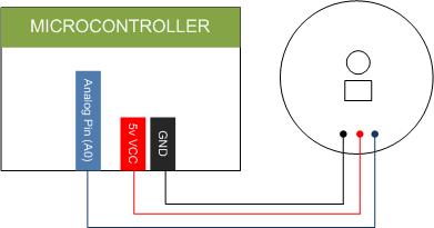
Wiring the Pulse Sensor:
Running the code library:
Before running the code you need to include or add the code library to your Arduino IDE. > extract the compress file and copy the folder and save it you Arduino code library then close your Arduino IDE and open again, now you can see the heart rate sensor code at your Code Library, for the Processing IDE, just extract the zip file and open it inside of Processing IDE and RUN the code.
Sample Code
Download the source code for Arduino here | ZIP
Download the source code for Processing here |ZIP
Download the starter guide documentation here | PDF
Download the schematics diagram here | PDF


