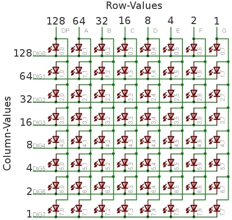
The 8×8 Matrix LED you can adjust brightness by using Arduino Sketch, the 8×8 LED has many applications in real life such as electronic display panel or signage display projects and display clock, etc. The LED matrix can be driven in two ways parallel or serial, in this test were going to use serial communication in order to save the interface. The serial driven matrix are dynamic it can display the LED MATRIX row by row or column by column. below are the device details and electronic parts required.
The MAX7221 and MAX7219
The MAX7221 and MAX7219 provide as easy way to control an array of 64 LEDs or up to 8 digit made of 7 SEGMENT display with a minimum of electronic components. These chip it has a single resistor and 1 or 2 capacitors, the data is send to the chip using a SPI compatible protocol using 3 of the digital pins on the Arduino. If you going to control more that 8 7SEGMENT display or more than 64 LEDS the chip can be cascaded. The library witch has been used on this demo can support up to 8 cascaded device, which add up to 512 LEDS that be light individually using 3 pins on your Arduino. The MAX7221 or MAX7219 is more suitable for controlling LEDS, if you’ll going to switch from Arduino to a different controller you need to use the MAX7221, this chip support fully SPI compatible interface. The library which is use on this lab can cope both types of devices, and the visual appearance are both same.
If you want to learn more about the MAX7XXX series, just download the components datasheets below.
8×8 Matrix LED
8X8 MATRIX LED MODULE w/d MAX7219
Electronic Parts
- 8×8 LED Matrix
- MAX7219
- 10uF 25V Electrolytic capacitor
- 10K Resistor
- 0.1uF Capacitance Ceramic Capacitor
- Headers and receptacles.
Schematics Diagram
Specification of LED MTRIX Module
- Operating Voltage > DC 4.7 v ~ 5.3v | Typical Voltage: 5v
- Operating Current > 320mA | Max Operating Current: 2A
- Operating Temperature > 0 Degree Celsius ~ 50 Degree Celsius | Typical Temperature: 25 Degree Celsius
Wiring Diagram
Demo Code
[crayon-680ffcfe673d9253172778/]
Download the source code here | ZIP
Download the MAX7XXX code library here | ZIP
Download the Datasheet here | PDF

