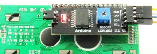
Using I2C (I square C) in Arduino interface , I2C is a standard for connection MCU and peripherals together. I2C is sometimes referred to as 2 wire interface or TWI. All the Arduino board have at least 1 I2c socket which you can attach any peripherals that use I2C. examples are LCD with I2C module, Matrix LCD, 7 Segment Display, Real Time Clock modules, PWM(Pulse with Modulation Module) any modules and device that support I2C can be used in Arduino.
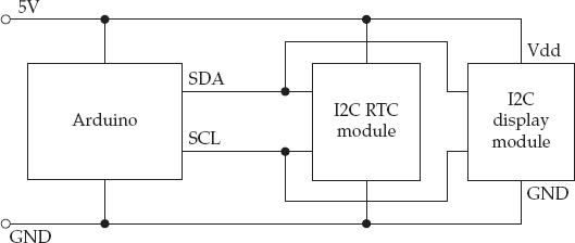
The I2C is defined as a BUS because its uses is not limited to connecting one component directly to another. Say you have a display connected to MCU; using the same two bus pins, you can connect a whole set of slave devices to a master device and Arduino will act as the master and each of the slaves has a unique address that identifies the devise on the bus, you can also connect two Arduino together using I2C so they can exchange data,
The I2C Device
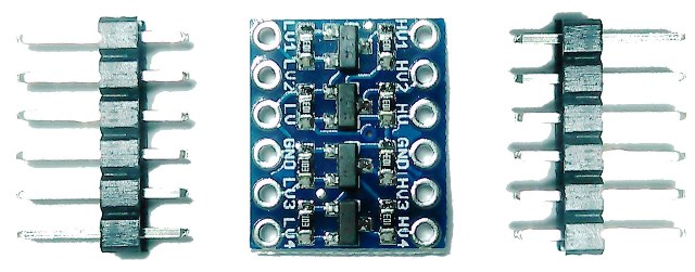
I2C connection lines from a MCU and I2C from the module can act as both a digital output or digital input called tri-state. In tri-sate mode, the connection are neither High or Low. The output also called Open-Collector, which means that should be requires a pull-up 4.7 kOhms resistors, and there should be one pair for I2C Bus, pulling up to either 3.3v or 5v, depending on the voltage you want to operate. If the device run on different voltages, you need to use a level converter or a bidirectional level converter module suitable for I2C.
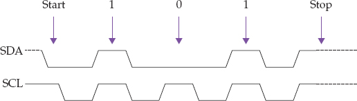
I2C(I square C) Protocol
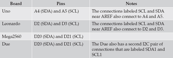
I2C or I square C requires or use 2 wires to transmit and receive data. These 2 wires are called the Serial Clock Line or SCL and SDA or Serial Data Line. See below the timing diagram for this signal, as you can see the master supplies the SCL clock and when there is data to be transmitter the sender or master or slave takes SDA line out of tri state digital input mode and sends the data as logic high or low in time with clock signal. When the transmission is complete, the clock can stop and the Serial Data Line pin is returned to tri state.
Using Wire Library on I2C Bus
To make I2C works of Arduino you need to import the Wire Libary , can be use to generate pulses turning digital output on and off in your code. The wire library can handles all the timing complexity to send and receive bytes of data.


