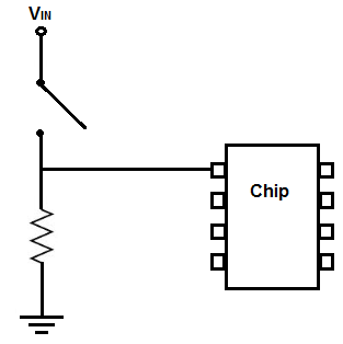
A Pull-Down resistor is a resistor that makes the Pin of the chip will become normally LOW and it turn it going to HIGH when switched on. Pull-Up or Pull-Down resistor are mostly they are connected to the pins of the chip so that they can define the state of the pins, the pin of the chip can be in any 3 states, they can be LOW, or below half of the voltage fed into the power supply of the chip. The pins can be HIGH when voltage above half, or pins can be floating meaning they are unconnected to either LOW or HIGH voltage. In Pull-Down resistor the pin may go randomly between LOW or HIGH. Pins may float because they have no clear define voltage signal going into it. External noises may allow it to randomly take on both values. This is way we normally want the signal going into the pin to be clearly defined. then we’re assure that whether it is LOW or HIGH.
A Pull-Up resistor is to pull the pin into a HIGH state.
A Pull-Down resistor is to pull the pin into a LOW state.
When connected to a push-button, the state of the pins can be switch on, we will going to illustrate how to connect a Pull-Down resistor to the chip.
We will going to connect a pull down resistor to a pin of a chip so that a pin can be normally LOW and then switch high when a switch such as a push button is pushed down, the best way to illustrate the Pull-Down resistor is using logic IC chip that works purely base on LOW or HIGH signals. see below the schematics diagram.
Required component to this illustration
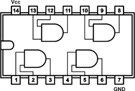
SN7108 AND Gate IC Chip – The SN5408, SN54LS08, and SN54S08 are characterized for operation over the full military temperature range of -55°C to 125°C. The SN7408, SN74LS08 and SN74S08 are characterized for operation from 0° to 70°C.
2x 10K Ohms Resistor
330 Ohms Resistor
2x Push Buttons
1x LED

Each AND Gate has two inputs and one output. In this illustration We will going to use two push button as our inputs to NAND gate, the value will that we will use for the Pull-Down resistor is 10k Ohms. The LED and the 330 resistor we will going to connect so that we need to limit the current pass true the LED so that it will not burn.
The Pull-Down resistor circuit can be used exactly as is for your all pull-down resistor circuit. The pin will be LOW normally and when the switch is close it become HIGH, When the Push Button is open, it is connected directly to the ground then obviously will turn the logic to LOW level. When the switch is closed, the voltage from the power source falls across the resistor, thus the pin of the pin chip is drawn to a HIGH state.
A schematics diagram with 2 Pull-Down Resistor

Wiring the Pull-Down resistor with SN7108 AND Gate

You need to provide a +5v to pin 14 and connect the pin 7 to the GND. This will establish a power to the chip, next is connect the Pull-Down resistors to each of the inputs to AND gate. A Pull-Down resistor circuit first has a resistor connected to + voltage then a push button connected to ground. When the push-button is not push, each of the pins of the AND gate will be LOW when a switch is pressed down, the resistor will gets the voltage dropped and the pin of the AND gate will be HIGH, the AND gate logic will both inputs must be HIGH. Therefore you must press down on both push button in order for the circuit will work.
Download the Datasheet of SN7108 AND Gate | Pdf


