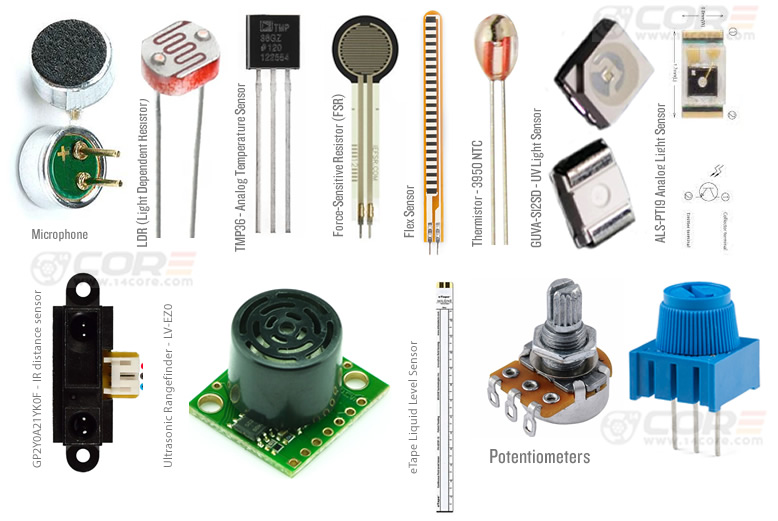
Analog sensors are run by measuring a physical object, chemicals, pressure, temperature, weight, etc. This device works by converting analog voltage and converted to digital signals that your computer or microcontroller can understand. Many sensors have a respective formula that describes the connection between their voltage output functionality and reading values. All analog sensors have documentation of how to operate including formulas high enough to get exact correct readings. However, some analog sensors already define the purpose, but it requires calibrating before it can be used and gathering the proper precise readings, some are required you to generate your own formula for each individual sensor, this process called calibration is a very important stage to achieve precise accuracy.
How to calibrate an Analog Sensor
Basically, the connection between the output voltage of the analog sensor and the measuring parameter can be defined by some functions. In order to determine what is the given values of readings. First thing first we need to gather first data from the sensor before we can calculate the precise and accurate data to fits-in. Below is the test code for gathering data and calibrating an analog sensor using your microcontroller.
Analog Sensor Calibration
First, you need to get the highest and lowest reading value from the sensor to find its operating range at the current requirements. For this example, we can test using an analog sensor such as a photoresistor or potentiometer will fit. Don’t forget that you need to get readings from Analog 0.
[crayon-691d9bd7b9f08905249418/]
Precise Analog Sensor Reading
The example below will demonstrate how to read any analog sensor such as a Photoresistor or Potentiometer accurately, The analog pin with is will be marked as 0 of the sensor and will be read, and calculated according to its average using an array to keep track of the last reading value.
[crayon-691d9bd7b9f11001908910/]


