This guide we will going extend / amplify the 433 MHz radio signal with MAX263AXT. However, HC-12 alone already reach to 2KM (2000 meter in open range ) so perhaps we can extend it more with the help of MAX263AXT LNA. The MAX2634 LNA (Low-Noise Amplifier) combined with low-power shutdown mode enhanced for 308MHz, 315MHz, and 433MHz Frequency, suited for remote-controlled devices such as RKE(Remote Key-less Entry), Security Devices, Garage Door Openers, Telemetry Receivers, Tire Pressure Monitoring, Radio Controlled Devices, Radio Controlled Switches. In addition, this device is designed for automotive use which is why it is suitable for any harsh environment that can be operated from the temperature range of -40°C to +125°C.
One of the best feature of this chip is was reduces the required components, just a single inductor to match the input frequency best noise formation and input return loss. additionally integrated logic-controlled low-power shutoff mode to reduce the power consumption however, adding 0.1µA includes replacing two transistors to add a shutoff function in discrete-based LNA solutions. At 315MHz application, the LNA reach to 15.5dB power gain and a 1.25dB noise figure while consuming only 2.5mA of supply current of 3v to 5v supply voltage. The MAX2634 LNA optimizes for four frequency such as 308MHz, 315MHz, 418MHz, and 433.92MHz that runs on 2.2v to 5.5v operating current of 2.5mA ~ 4mA including 1µA Logic-controlled shutoff plus 1.25dB Noise Figure, -16Bm Input IP3, and 15.5dB Power Gain. for more technical details please refer to the datasheet below.
Testing Requirements
- Arduino IDE | PlatformIO
- Test Boards :
- Note: Wiring with microcontroller please refer to HC-12 / HC-11
- MAX263AXT LNA
- Resistors (See below diagram for required value)
- Capacitors(See below diagram for required value)
- Inductor (See below diagram for required value)
- Antenna Connector
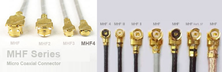
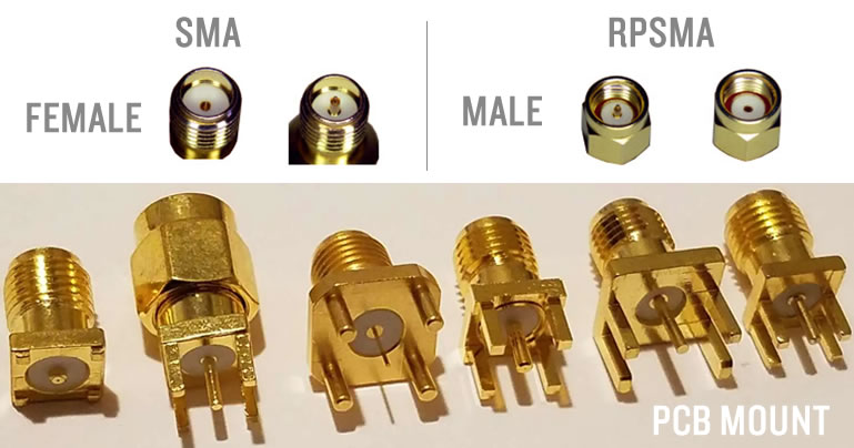
Connectors and Antenna
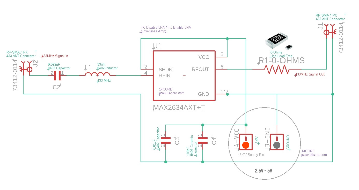
Wiring Guide
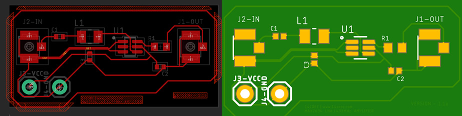
PCB Board Milling / Gerber File
Parts List / Bill of Material
- 0. MAX2634AXT LNA
- 1. J1 – U.FL-R-SMT(01) UFL Connector Male Pin
- 2. J2 – U.FL-R-SMT(01) UFL Connector Male Pin
- 3. C1 – 0.022uF – 0402 Capacitor
- 4. L1 – 33nH – 0402 Inductor
- 5. C2 – 0.01uF – 0402 Capacitor
- 6. C3 – 100pF – 0402 Capacitor
- 7. R1 – 0 Ohms – 0402 Resistor (Use led-free parts)
- Download PCB Milling File | Gerber
- Download Gerber Viewer | Windows | Linux
Downloads
View / Download MAX263AXT | PDF


