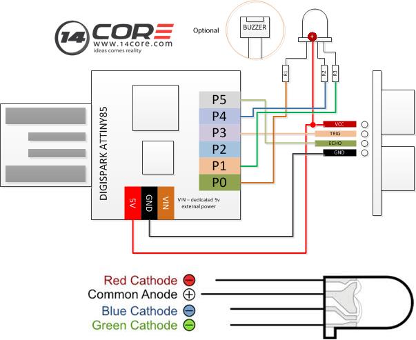
In this illustration we will going to wire the Digispark ATTiny Development Board with HC-SR04 Ultrasonic range detector, as our output we will going to use an RGB LED when the objects is near or closer to the sensor the RGB LED will going to switch on and if it is out of range the blue will light on. In the example below we can used a dedicated 5v power to supply 5v to our Digispark ATTiny Board.
Required Components
1x Digispark ATTiny Board
1x HCSR04 Ultrasonic Range Detector
1x RGB LED
1x Jumper Wire
1x Solder less Bread Board
Wiring Diagram
Arduino Sketch
1 2 3 4 5 6 7 8 9 10 11 12 13 14 15 16 17 18 19 20 21 22 23 24 25 26 27 28 29 30 31 32 |
#include <NewPing.h> //Iclud Arduino Pin Library #define TRIGGER_PIN 3 //HCR04 Trigger set to pin 3 #define ECHO_PIN 5 // HCR04 Echo set to Pin 5 #define RED_PIN 0 // Red light set to Pin 0 #define GREEN_PIN 1 // Green Light set to Pin 1 #define BLUE_PIN 4 // Blue light set to Pin 4 #define DISTANCE 60 // Distance value NewPing sonar(TRIGGER_PIN, ECHO_PIN, DISTANCE); void setup() { pinMode(RED_PIN, OUTPUT); pinMode(GREEN_PIN, OUTPUT); pinMode(BLUE_PIN, OUTPUT); } void loop() { uint8_t distance = sonar.ping_cm(); if (distance) { uint8_t greenValue = map(distance, 1, DISTANCE, 0, 255); // Mapping the distance range of 0 to 255 Pulse with Modulation value for the green LED uint8_t redValue = 255 - greenValue; analogWrite(GREEN_PIN, greenValue); analogWrite(RED_PIN, redValue); digitalWrite(BLUE_PIN, LOW); } else { digitalWrite(GREEN_PIN, LOW); // GREEN LIGHT Off Out of reading distance range digitalWrite(RED_PIN, LOW); // RED LIGHT off digitalWrite(BLUE_PIN, HIGH); // BLUE LIGHT On } delay(100); } |
Didispark ATTiny85 with Ultrasonic HC SR04 Sensor
Great, simple and illustrative project! I almost missed the resistors, and they are not listed in the parts list. I expect something like 100ohm will work.
I was looking for something simple to try with my ATtiny and HC-SR04 and this is it!
Thanks!
D
why ground of LED connect to VCC, not to ground?